COMPONENT LOCATION
GENERAL DESCRIPTION

The value of the input shaft speed should be equal to the value of the output shaft speed, when multiplied by the 1st gear ratio, while the transaxle is engaged in the 1st gear. For example, if the output speed is 1000 rpm and the 1st gear ratio is 2.842, then the input speed is 2,842 rpm.

DTC DESCRIPTION

This code is set if the value of input shaft speed is not equal to the value of the output shaft, when multiplied by the 1st gear ratio, while the transaxle is engaged in 1st gear. This malfunction is mainly caused by mechanical troubles.

DTC DETECTING CONDITION

Item

Detecting Condition & Fail Safe

Possible cause

DTC Strategy

● 1st gear incorrect ratio

● Faulty Input speed sensor

● Faulty output speed sensor

● Faulty UD clutch or LR brake or Oneway clutch

Enable Conditions

● Engine speed >450rpm

● Output speed >350rpm

● Shift stage 1st. gear

● Input speed >0rpm

● A/T oil temp sensor voltage <4.5V

● Voltage of Battery >10V

● TRANSAXLE RANGE SWITCH is normal

Threshold value

●ㅣinput speed/1st gear ratio - output speed|≥200rpm /1st. gear ratio

Diagnostic Time

● more than 1sec

Fail Safe

● Locked into 3 rd gear.(If diagnosis code P0731 is output four times, the transaxle is locked into 3rd gear)

MONITOR SCANTOOL DATA
1.

Connect scantool to data link connector(DLC)

2.

Engine "ON".

3.

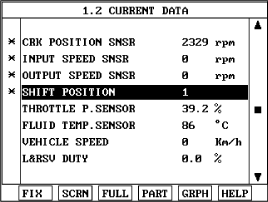
Monitor the "ENGINE SPEED, INPUT SPEED SENSOR, OUTPUT SPEED SENSOR, GEAR POSITION" parameter on the scantool

4.

Perform the "STALL TEST" with gear position "1"

Specification : 2000~2700 engine rpm
OPERATING ELEMENT OF EACH SHIFTING RANGE

UD/C

OD/C

REV/C

2ND/B

LR/B

OWC

P

R

N

D1

D2

D3

D4

※ Low & Reverse Brake is released When the Vehicle speed over the 5 MPH(7Km/h)

Stall test procedure in D1 and reason

Procedure

A.

Warm up the engine

B.

After positioning the select lever in "D" ,depress the foot brake pedal fully after that, depress the accelerator pedal to the maximum

* The slippage of 1st gear operating parts can be detected by stall test in D

Reason for stall test

A.

If there is no mechanical defaults in A/T, every slippage occur in torque converter.

B.

Therfore, engine revolution is output, but input and output speed revolution must be "zero" due to wheel's lock.

C.

If 1st gear operating part has faults, input speed revolution will be out.

D.

If oupput speed revolution is output. It means that the foot brake force is not applied fully. Remeasuring is required.

Does "STALL TEST " within specification?

▶ Go to "W/Harness Inspection" procedure

▶ Go to "Component inspection" procedure

caution

● Do not let anybody stand in front of or behind the vehicle while this test is being carried out.

● Check the A/T fluid level and temperature and the engine coolant temperature.

-

Fluid level : At the hot mark on the oil level gauge.

-

Fluid temperature : 176 °F~ 212 °F (80~100 °C).

-

Engine coolant temperature : 176 °F~ 212 °F (80~100 °C).

● Chock both rear wheel(left and right).

● Pull the parking brake lever on with the brake pedal fully depressed.

● The throttle should not be left fully open for more than eight second.

● If carrying out the stall test two or more time, move the select lever to the "N" position and run the engine at 1,000 rpm to let the A/T fluid cool down before carrying out subsequent.

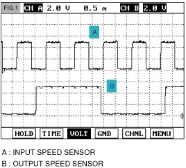
SIGNAL CIRCUIT INSPECTION
1.

Connect Scantool

2.

Engine "ON" .

3.

Monitor signal waveform of the "INPUT & OUTPUT SPEED SENSOR" after shifting to D1 range

Does "INPUT & OUTPUT SPEED SENSOR" follow the referance data?

▶ Go to "Component Inspection" procedure

▶ Check for electrical niose of circuit in INPUT & OUTPUT SPEED SENSOR or Replace INPUT & OUTPUT SPEED SENSOR. Repair as necessary and Go to "Verification Vehicle Repair" procedure

COMPONENT INSPECTION
1.

Connect Oil pressure guage to "UD" and "L/R" port.

2.

Engine "ON".

3.

Drive a car with gear position 1 in "SPORTS MODE".

4.

Compare it with referance data as below

Specification : shown below

Measurement condition

Standard hydraulic pressure kPa (psi)

Selector lever position

Shift position

Engine speed (rpm)

Under drive clutch pressure

Reverse clutch pressure

Overdrive clutch pressure

Low and reverse brake pressure

Second brake pressure

Torque converter pressure

P

-

2,500

-

-

-

310-390

(45-56)

-

250-350

(36-56)

R

Reverse

2,500

-

1,270-1,770

(185-256)

-

1,270-1,770

(185-256)

-

500-700

(185-256)

N

2,500

-

-

-

-

310-390

(45-56)

-

250-390

(36-56)

D

1st gear

2,500

1,010-1,050

(146-152)

-

-

*1,010-1,050

(146-152)

-

500-700

(73-101)

2nd gear

2,500

1,010-1,050

(146-152)

-

-

-

1,010-1,050

(146-152)

500-700

(73-101)

3rd gear

2,500

590-690

(85-100)

-

590-690

(85-100)

-

-

450-650

(65-94)

4th gear

2,500

-

-

590-690

(85-100)

-

590-690

(85-100)

450-650

(65-94)

*L&R brake applied 0-3 mph only in D1

Is oil pressure value within specification?

▶ Repair AUTO TRANSAXLE(Clutch or Brake) as necessary and Go to "Verification Vehicle Repair" procedure.

▶ Replace AUTO TRANSAXLE (BODY CONTROL VALVE faulty) as necessary and Go to "Verification Vehicle Repair " procedure.

VERIFICATION OF VEHICLE REPAIR

After a repair, it is essential to verify that the fault has been corrected.

1.

Connect scan tool and select "Diagnostic Trouble Codes(DTCs)" mode.

2.

Using a scantool, Clear DTC.

3.

Operate the vehicle within DTC Enable conditions in General information.

Are any DTCs present ?

▶ Go to the applicable troubleshooting procedure.

▶ System performing to specification at this time.

Яндекс.Метрика