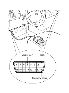
Connector the Hi-scan (pro) to the 16P data link connector located the driver'd side kick panel.
This specification applies to HCU(Hydraulic Control Unit) and ECU(Electronic Control Unit) of the HECU.(Hydraulic and Electronic Control Unit)
This specification is for the wiring design and installation of ABS/TCS/ESP ECU.
This unit has the functions as follows.
Input of signal from Pressure sensor, Steering angle sensor, Yaw & Lateral G sensor,the wheel speed sensors attached to each wheel.
Control of braking force / traction force/ yaw moment.
Failsafe function.
Self diagnosis function.
Interface with the external diagnosis tester.
Installation position : engine room
Brake Pipe length from Master cylinder port to HECU inlet port should be max. 1m
The position should not be close to the engine block and not lower than the wheel.
The ECU shall be put into operation by switching on the operating voltage (IGN).
On completion of the initialization phase, the ECU shall be ready for operation.
In the operating condition, the ECU shall be ready, within the specified limits (voltage and temperature), to process the signals offered by the various sensors and switches in accordance with the control algorithm defined by the software and to control the hydraulic and electrical actuators.
The ECU shall receive wheel speed signal from the four active wheel sensors.
The wheel signals are converted to voltage signal by the signal conditioning circuit after receiving current signal from active wheel sensors and given as input to the MCU.
Overvoltage
When overvoltage is detected(above 16V), the ECU switches off the valve relay and shuts down the system.
When voltage is returned to operating range, the system goes back to the normal condition after the initialization phase.
Undervoltage
In the event of undervoltage(below 10V), ABS control shall be inhibited and the warning lamp shall be turned on.
When voltage is returned to operating range, the warning lamp is switched off and ECU returns to normal operating mode.
The ECU performs a pump motor test at a speed of 12km/h once after IGN is switched on.
Failures detected by the ECU are encoded on the ECU, stored in a EEPROM and read out by diagnostic equipment when the ignition switch is turned on.
The diagnosis interface can also be used for testing the ECU during production of the ECU and for actuating the HCU in the test line of manufactories (Air-bleeding line or Roll and Brake Test line).
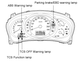
The active ABS warning lamp module indicates the self-test and failure status of the ABS.
The ABS warning lamp shall be on:
During the initialization phase after IGN ON. (continuously 3 seconds).
In the event of inhibition of ABS functions by failure.
During diagnostic mode.
When the ECU Connector is seperated from ECU.
The active EBD warning lamp module indicates the self-test and failure status of the EBD.
However, in case the Parking Brake Switch is turned on, the EBD warning lamp is always turned on regardless of EBD functions.
The EBD warning lamp shall be on:
During the initialization phase after IGN ON. (continuously 3 seconds).
When the Parking Brake Switch is ON or brake fluid level is low.
When the EBD function is out of order.
During diagnostic mode.
When the ECU Connector is seperated from ECU.
The TCS warning lamp indicates the self-test and failure status of the TCS.
The TCS warning lamp is turned on under the following conditions.
During the initialization phase after IGN ON. (continuously 3 seconds).
In the event of inhibition of TCS functions by failure.
When driver trun off the TCS function by on/off switch.
During diagnostic mode.
The TCS function lamp indicates the self-test and operating status of the TCS.
The TCS Function lamp operates under the following conditions :
During the initialization phase after IGN ON. (continuously 3 seconds).
When the TCS control is operating. (Blinking - 2Hz)
The TCS On/Off Switch shall be used to toggle the TCS function between On/Off states based upon driver input.
The On/Off switch shall be a normally open, momentary contact switch.
Closed contacts switch the circuit to ignition.
Initial status of the TCS function is on and switch toggle the state.
Turn the ignition switch OFF.
Connector the Hi-scan (pro) to the 16P data link connector located the driver'd side kick panel.

Turn the ignition switch ON.
Check for diagnostic trouble using the Hi-scan(pro).
After completion trouble of the repair or correction of the problm, erase the stored fault codes the clear key on the Hi-scan(pro).
Disconnect the Hi-scan (pro) from the 16P date link connector.
NORMAL BRAKING without ABS
Solenoid valve | State | Valve | Passage | Pump motor |
Inlet valve (NO) | OFF | OPEN | Master cylinder ⇔ Wheel cylinder | OFF |
Outlet valve (NC) | OFF | CLOSE | Wheel cylinder ⇔ Reservoir |
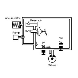
When braking, the hydraulic pressure in the TMC is increased. The pressure reaches the wheel brake via the current less open inlet valve IV. The current less closed outlet valve OV is closed. For the sake of simplicity the diagram is limited to only the solenoid valve pair of one brake circuit. The wheel speed is reduced as the brake pressure increases, in the extreme case until the wheel locks.
With ABS
DUMP MODE
Solenoid | State | Valve | Passage | Pump motor |
Inlet valve (NO) | ON | CLOSE | Master cylinder ⇔ Wheel cylinder | ON |
Outlet valve (NC) | ON | OPEN | Wheel cylinder ⇔ Reservoir |
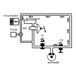
If the wheel speed decreases, there is still a tendency to lock; the brake pressure on the corresponding wheel must be reduced accordingly. For this, the outlet valve OV is opened, the inlet valve IV remains closed.
The brake pressure to the low-pressure accumulator is reduced. The wheel in danger of locking gains speed again.
HOLD MODE
Solenoid | State | Valve | Passage | Pump motor |
Inlet valve (NO) | ON | CLOSE | Master cylinder ⇔ Wheel cylinder | ON |
Outlet valve (NC) | OFF | CLOSE | Wheel cylinder ⇔ Reservoir |
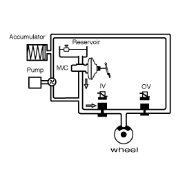
When a wheel (or several) tends to lock the inlet valve IV is first closed to avoid a further increase in brake pressure. The outlet valve OV remains closed: the brake pressure is kept constant.
INCREASE MODE
Solenoid | State | Valve | Passage | Pump motor |
Inlet valve (NO) | OFF | OPEN | Master cylinder ⇔ Wheel cylinder | ON |
Outlet valve (NC) | OFF | CLOSE | Wheel cylinder ⇔ Reservoir |
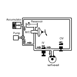
For optimum brake from the certain wheel acceleration a brake pressure increase is necessary. For this, the inlet valve IV is opened and the outlet valve OV is closed. The pump of the unit starts to run and aspirates the necessary quantity of fluid from the Lowpressure accumulator, in order to produce the necessary brake pressure for the pressure increase phase in seconds.
With an increase in the brake pressure the wheel speed is reduced. These control phases are repeated until the ABS control unit no longer detects any tendency of the wheels to lock.
During ABS control function, the brake pedal only moves in accordance with the volume requirement of the wheels. Because of a sudden change in friction coefficient this pedal movement may increase slightly.
Fail Safe Funtion
If there is a problem with the ABS system, the Failsafe function operates, turning off the relay which supplies the power to the solenoid valve, stoping the output of the control signal, and turning on the ABS warning lamp in order to warn the user of malfunction of the ABS system.
Conventional brake system operates under the circumstance.
FUNCTION
Main performance
Traction: Lower vibration and higher launchability, acceleration and climbability by slip control.
Cornering and passing: Stable cornering and passing.
Steering stability: Control traction force traverse vector prior to provide easy turning when turning the steering wheel.
General TCS features
Improved drivability. Minor operation of acceleration is not necessary in launching and acceleration on slippery road.
More stable cornering by stable acceleration on normal road condition.
TCS system will compare vehicle speed received from rear wheel speed sensor and driving wheel speed from front wheel speed sensor on slippery road condition, and provide optimum slipping rate of driving wheels.
FULL TRACTION CONTROL SYSTEM (FTCS)
The TCS control module (HECU) controls TCS control. It includes ABS control module.
HECU will compare signals from front (driving) and rear wheel speed sensors to detect driving wheels slip.
Upon detecting driving wheels slip, HECU will perform TCS control. The TCS control will include brake TCS (BTCS) control.
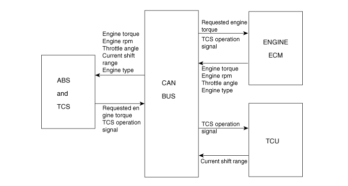
HECU will transmit engine torque reduction request, fuel cut cylinder number, and TCS control request signals in accordance with slip level to engine ECM and TCM through BUS line which will provide CAN communication for TCS control.
Engine ECM will perform fuel cut as requested by HECU and retard ignition timing as per engine torque reduction request signal.
TCM will hold shift position by TCS control time according to TCS operation signal. Then enhanced acceleration by kick-down will not occur.
On TCS control, only brake control will be performed. (engine and TCM control will not happen)
Controlled by motor pump output pressure.
NORMAL MODE
Solenoid valve | State | Valve | Motor pump | TC valve |
Inlet (NO) | OFF | OPEN | OFF | OFF |
Outlet (NC) | OFF | CLOSE |
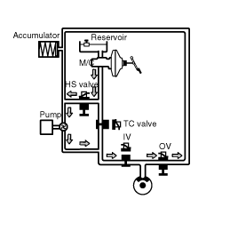
In the normal driving condition, TC valve (normally open) is the passage between the master cylinder and the each wheel cylinder.
When brake pedal is applied, brake pressure is delivered to the wheel cylinders via NO-TC valve and all solenoid valves inside the hydraulic unit are deactivated.
In case of TCS malfunction, it does not affect brake operation.
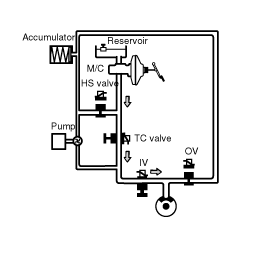
PRESSURE INCREASE MODE
Solenoid valve | State | Valve | Motor pump | TC valve |
Inlet (NO) | FRONT: OFF REAR: ON | FRONT: OPEN REAR: CLOSE | ON | ON |
Outlet (NC) | OFF | CLOSE |
If a front wheel spin is detected, TCS begins a brake control to decrease a wheel spin.
Hydraulic shuttle valve (HSV) is opened.
Brake fluid is supplied from the master cylinder by motor operation to the spin wheel via HSV.
TC valve is closed (ON).
Brake pressure generated from motor pump is delivered only to the front wheel.
Inlet valve remains open to deliver the brake pressure generated from motor pump to the spinning wheels.
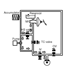
PRESSURE DUMP MODE
Solenoid valve | State | Valve | Motor pump | TC valve |
Inlet (NO) | ON | CLOSE | ON | ON |
Outlet (NC) | FRONT : ON REAR : OFF | FRONT : OPEN REAR : CLOSE |
When the wheel deceleration is under the threshold and the wheel spin is reduced under a slip threshold, applied brake pressure is reduced to get an optimum traction force.
Outlet valve is open to release the brake pressure and inlet valve is closed to block the pressure increase from the motor pump.
Hydraulic shuttle valve (HSV) remains opened, TC valve is ON.
Motor is ON, to dump the brake fluid being released from the lock-up wheel.
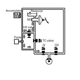
PRESSURE HOLD MODE
Solenoid valve | State | Valve | Motor pump | TC valve |
Inlet (NO) | ON | CLOSE | ON | ON |
Outlet (NC) | OFF | CLOSE |
