Description

If Main relay is not operated normally, possible causes are abnormal IG "ON" signal, ECM power, ECM ground and faulty ECM. If Main relay does not work normally, ECM is not operated. Therefore trouble shooting by using the scantool is impossible.

Diagnostic Procedure
IG "ON" power inspection
1.

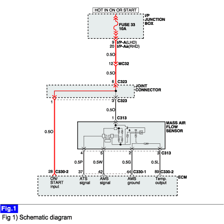
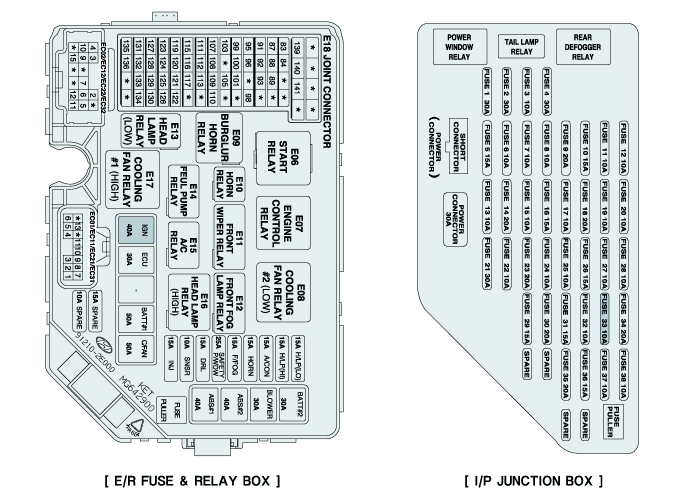
Inspect IG1 fusible link (40A) on the E/R compartment junction box and fuse 33 (10A) on the I/P junction box.

A.

Case 1 : In case that fuse and battery power is normal.

Go to "Next procedure" as below.

B.

Case 2 :

In case that IGN fusible link (40A) is blown. : Repair short to ground in IGN power supply circuit between ignition switch connector (M18) terminal "6" and I/P junction box connector I/P-D, LHD (I/P-Da ,RHD) terminal "11 (12)".

In case that fuse 33 (10A) is blown. : Repair short to ground in IGN power supply circuit related with joint connector (C323).

2.

Inspect "IGN" power at terminal "28" after disconnecting ECM connector (C330-2).

caution

"ECM Connector Inspection" of "Details Inspection(Equipment Setting)" reference

A.

IG "ON" : 11.5V~13.0V

IG "OFF" : Below 0.2V

B.

Case 1 : In case that IG "ON" power at ECM connector (C330-2) terminal "28" is normal, When IG KEY is switched "ON" ↔ "OFF".

Go to "Main relay circuit inspection" procedure.

C.

Case 2 : In case that IG "ON" power at ECM connector (C330-2) terminal "28" is abnormal, When IG KEY is switched "ON" ↔ "OFF".

Repair open in IGN power supply circuit between fuse 33 (10A) on the I/P junction box and ECM connector (C330-2) terminal "28".

Яндекс.Метрика