Remove the rear wheel and tire(A) from rear hub(B).
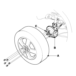
Be careful not to damage the hub bolts(C) then remove the rear wheel and tire(A).
Loosen the wheel nuts slightly
Raise the rear of the vehicle, and make sure it is securely supported.
Remove the rear wheel and tire(A) from rear hub(B).

Be careful not to damage the hub bolts(C) then remove the rear wheel and tire(A).
Remove the caliper mounting bolts(A), and hang the caliper assembly(B) to one side. To prevent damage to the caliper assembly or brake hose, use a short piece of wire to hang the caliper from the undercarriage.
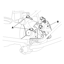
Remove the wheel speed sensor(B) from the axle carrier(A).
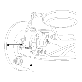
Loosen the brake disc mounting screw(A), and then remove the brake disc(C) from the hub(B).
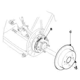
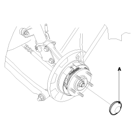
Using a (-)screwdriver, remove the hub cap(A).
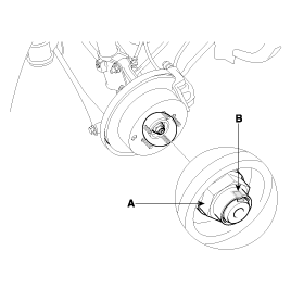
Remove the hub bearing flange nut(A).
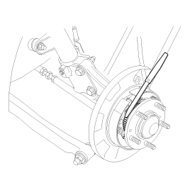
Using a flat-tipped (-)screwdriver, spread out the groove(B) on the flange nut(A)
Loosen the hub bearing flange nut(A).
Remove the rear hub washer(A) and rear hub assembly(B).
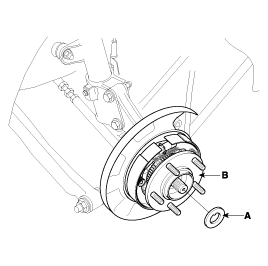
Be careful not disassembly the rear hub assembly.
For vehicles equipped with ABS.
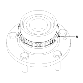
Care must be taken not to scratch or damage the teeth of the rotor.
The rotor must never be dropped.
If the teeth of the rotor are chipped, it results in deformation of the rotor. It will make it impossible to detect the wheel rotation speed accurately and to operate the system normally.
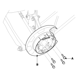
Loosen the rear dust cover mounting bolts(A) and then remove the rear parking brake assembly(B).
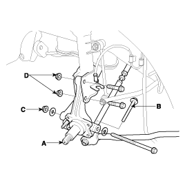
Remove the rear axle carrier(A).
Remove the trailing arm mounting bolt(B).
Remove the suspension arm mounting nut(C).
Remove the strut mounting nuts(D).
Loosen the wheel nuts slightly.
Raise the rear of the vehicle, and make sure it is securely supported.
Remove the rear wheel and tire(A) from rear hub(B).
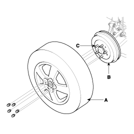
Be careful not to damage the hub bolts(C) then remove the rear wheel and tire(A).
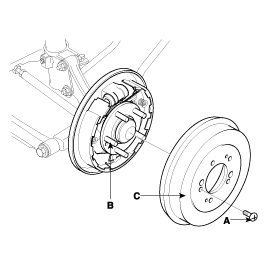
Loosen the brake drum mounting screw(A), and then remove the brake drum(C) from the hub(B).
Using a (-)screwdriver, remove the hub cap(A).
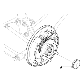
Remove the hub bearing flange nut(A).
Using a flat-tipped (-) screwdriver, spread out the groove(B) on the flange nut(A).
Loosen the hub bearing flange nut(A).
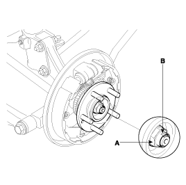
Remove the rear hub washer(A) and rear hub assembly(B).
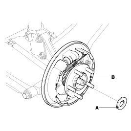
Loosen the rear dust cover mounting bolts(A) and then remove the drum brake assembly(B).
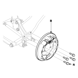
Remove the rear axle carrier(A).
Remove the trailing arm mounting bolt(B).
Remove the suspension arm mounting nut(C).
Remove the strut mounting nuts(D).

Install the rear axle carrier(A).
Install the strut mounting nuts(D).
Tightening torque
140 ~ 160Nm (1400 ~ 1600Kgf.cm, 103.3 ~ 118.0lbf.ft)
Install the suspension arm mounting nut(C).
Tightening torque
160 ~ 180Nm (1600 ~ 1800Kgf.cm, 118.0 ~ 132.8lbf.ft)
Install the trailing arm mounting bolt(B).
Tightening torque
100 ~ 120Nm (1000 ~ 1200, 73.8 ~ 88.5lbf.ft)

Replace the self-locking nut with new ones after removal.
Install the rear dust cover(B) and then tighten the mounting bolts(A).
Tightening torque
50 ~ 60Nm (500 ~ 600Kgf.cm, 36.9 ~ 44.3lbf.ft)

Install the hub assembly(B) and hub washer(A).

After tightening the hub bearing flange nut(A), caulk the concave portion(B) of the spindle by crimping the nut.
Tightening torque
200 ~ 260Nm (2000 ~ 2600Kgf.cm, 147.5 ~ 191.8lbf.ft)

Replace the flange nut with new ones after removal.
Install the hub cap(A).

Replace the hub cap with new ones after removal.
Installation of the rear speed sensor(A).(For vehicles equipped with ABS):
Insert a feeler gauge(C) into the space between the pole piece of the speed sensor(A) and the rotor teeth(B) surface, and then tighten the speed sensors(A) at the position where the clearance at all places is within the standard value.
Standard value
Clearance : 0.5 ~ 1.5mm (0.02 ~ 0.06in.)
Install the brake disc(C) from the hub(B), then tighten the brake disc mounting screw(A).
Tightening torque
5 ~ 6Nm (50 ~ 60, 3.7 ~ 4.4lbf.ft)

Install the brake caliper(B), then tighten the mounting bolt(A).
Tightening torque
50 ~ 60Nm (500 ~ 600Kgf.cm, 36.9 ~ 44.3lbf.ft)

Install the rear wheel and tire(A) on the rear hub(B).
Tightening torque
90 ~ 110Nm (900 ~ 1100kgf.cm, 66.4 ~ 81.2lbf.ft)

Be careful not to damage the hub bolts(C) then install the rear wheel and tire(A).
Install the rear axle carrier(A).
Install the strut mounting nuts(D).
Tightening torque
140 ~ 160Nm (1400 ~ 1600Kgf.cm, 103.3 ~ 118.0lbf.ft)
Install the suspension arm mounting nut(C).
Tightening torque
160 ~ 180Nm (1600 ~ 1800Kgf.cm, 118.0 ~ 132.8lbf.ft)
Install the trailing arm mounting bolt(B).
Tightening torque
100 ~ 120Nm (1000 ~ 1200Kgf.cm, 73.8 ~ 88.5lbf.ft)

Replace the self-locking nut with new ones after removal.
Install the rear dust cover(B), then tighten the mounting bolt(A).
Tightening torque
50 ~ 60Nm (500 ~ 600Kgf.cm, 36.9 ~ 44.3lbf.ft)

Install the rear hub assembly(B) and hub washer(A).

After tightening the hub bearing flange nut(A), caulk the concave portion(B) of the spindle by crimping the nut.
Tightening torque
200 ~ 260Nm (2000 ~ 26000Kgf.cm, 147.5 ~ 191.8lbf.ft)

Replace the flange nut with new ones after removal.
Install the hub cap(A).

Replace the hub cap with new ones after removal.
Install the brake drum(C) from the hub(B), then tighten the brake drum mounting screw(A).
Tightening torque
5 ~ 6Nm (50 ~ 60Kgf.cm, 3.7 ~ 4.4lbf.ft)

Install the rear wheel and tire(A) on the rear hub(B).
Tightening torque
90 ~ 110Nm (900 ~ 1100Kgf.cm, 66.4 ~ 81.2lbf.ft)

Be careful not to damage the hub bolts(C) then install the rear wheel and tire(A).
Inspection the play of the bearing while the vehicle is jacked up.
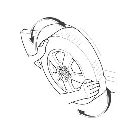
If there is any play, loosen the wheel nuts slightly. Raise the rear of the vehicle, and make sure it is securely supported.
Remove the rear wheel and tire(A) from rear hub(B).

Be careful not to damage the hub bolts(C) then remove the rear wheel and tire(A).
Remove the split pin(A), then remove castle nut(B) and washer(C) from the rear hub under applying the break.
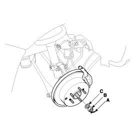
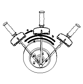
Tighten the hub bearing nut by the following procedures.
Hub bearing nut must be fastened with torque 28kgf.m and rear hub must be rotated above 3 times enough for secure placement of hub bearing.
Unfasten hub bearing nut until its tightening torque is 0Kgf.m
Hub bearing nut must be fastened again with torque 20Kgf.m
Assemble split pin.
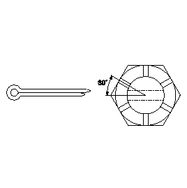
If the direction of split pin is not in line with the hole of knuckle unfasten hub bearing nut within 30° and assemble split pin
Inspection the play of the bearing while the vehicle is jacked up.

If there is any play, loosen the wheel nuts slightly. Raise the rear of the vehicle, and make sure it is securely supported.
Remove the rear wheel and tire(A) from rear hub(B).

Be careful not to damage the hub bolts(C) then remove the rear wheel and tire(A).
Remove the split pin(A), then remove castle nut(B) and washer(C) from the rear hub under applying the break.

Tighten the hub bearing nut by the following procedures.
Hub bearing nut must be fastened with torque 28kgf.m and rear hub must be rotated above 3 times enough for secure placement of hub bearing.
Unfasten hub bearing nut until its tightening torque is 0Kgf.m
Hub bearing nut must be fastened again with torque 20Kgf.m

Assemble split pin.
If the direction of split pin is not in line with the hole of knuckle unfasten hub bearing nut within 30° and assemble split pin
