COMPONENT LOCATION
GENERAL DESCRIPTION

At diesel, there is not a Trottle Position Sensor(TPS) but an Acceleration pedal Position Sensor(APS). As a standard of judgement about a driver's acceleration degree, APS signal is used at diesel where as, TPS signal is used at 2.0L gasoline engines or 2.7L gasoline engines. On both occations, the signals are inputted to 4WD ECM from ECM(PCM: 2.0L gasoline engine) through CAN.

This signal is used as a standard signal which decides torque distribution together with a steering angle sensor signal, a wheel speed sensor signal and a brake signal.

DTC DESCRIPTION

The DTC will set when there is no TPS(APS) signal or the signal is out of range.

DTC DETECTING CONDITION

Item

Detecting Condition & Fail Safe

Possible Cause

DTC Strategy

● Loss of signal out of range

ECM,TCCU connector looseness and poor terminal to wire connection.

CAN HIGH/LOW circuit open/short.

TPS faulty.

ECM malfunction.

TCCU malfunction.

Enable Conditions

● Message present 1.0 sec self clearing

Threshold Value

● No Signal or out of range

Diagnostic Time

● 1 Sec.

Fail safe

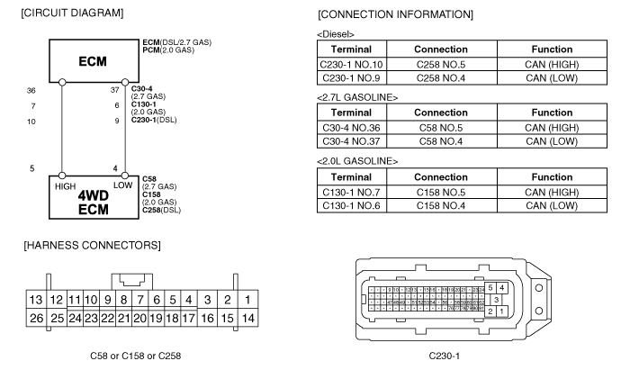
SCHEMATIC DIAGRAM
WAVEFORM INSPECTION
TERMINAL & CONNECTOR INSPECTION
1.

Many malfunctions in the electrical system may be caused from poor harness and terminals. These faults can be caused by interference from other electrical systems and mechanical or chemical damage.

2.

Thoroughly check connectors for looseness, poor connection, bending, corrosion, contamination, deterioration, or damage.

Has a problem been found?

▶ Repair as necessary and go to "Verification of Vehicle Repair" procedure.

▶ Go to the next procedure.

SIGNAL CIRCUIT INSPECTION
1.

CAN Signal Inspection

(1)

IG KEY : ON, Engine : OFF.

(2)

4WD ECM connector: connect.

(3)

Monitor signal waveform between terminal 4 and 5 of 4WD ECM harness connector.

(4)

Shift to N Range.

Specification : refer to 'Waveform Inspection'

Is CAN Signal display near the specified value?

▶ This may caused by intermittent fault. Verify data changibility by shaking the harness.

▶ Inspect ground to short of CAN Low ciruit.

▶ Inspect open or short of CAN Low circuit.

▶ Inspect ground to short of CAN High ciruit.

▶ Inspect open or short of CAN High circuit.

▶ Inspect TPS(or APS) in the ECM side.

▶ Check for ECM(or PCM) and replace it as necessary.

▶ Check for 4WD ECM and replace it as necessary.

2.

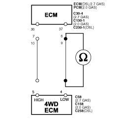
CAN Low open inspection

(1)

IG KEY OFF, ENG OFF

(2)

ECM and 4WD ECM connector : Disconnect.

(3)

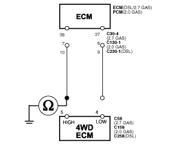
Measure resistance between terminal 4 of 4WD ECM harness connector and terminal 9(or 6 or 37) of ECM harness connector.

Specification : Approx. 0Ω

Is resistance display near the specified value?

▶ Proceed next inspection procedure.

▶ Repair open circuit of CAN Low comm. Line.

▶ If problem is solved, go to the "Verification of Vehicle Repair".

3.

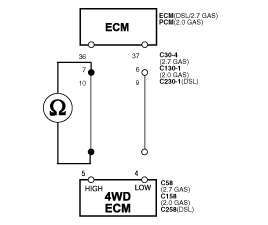
CAN High open inspection

(1)

IG KEY OFF, ENG OFF

(2)

ECM and 4WD ECM connector : Disconnect.

(3)

Measure resistance between terminal 5 of 4WD ECM harness connector and terminal 10(or 7 or 36) of ECM harness connector.

Specification : Approx. 0Ω

Is resistance display near the specified value?

▶ Proceed next inspection procedure.

▶ Repair open circuit of CAN High comm. Line.

▶ If problem is solved, go to the "Verification of Vehicle Repair".

Ground Circuit Inspection
1.

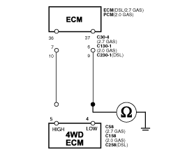
CAN Low circuit short to ground inspection

(1)

IG KEY ON, ENG OFF

(2)

ECM and 4WD ECM connector : Disconnect.

(3)

Measure resistance between terminal 4 of 4WD ECM harness connector and chassis ground.

Specification : Approx. ∞Ω

Is resistance display near the specified value?

▶ Proceed next inspection procedure.

▶ Repair ground to short circuit of CAN Low comm. Line.

▶ If problem is solved, go to the "Verification of Vehicle Repair".

2.

CAN High circuit short to ground inspection

(1)

IG KEY OFF, ENG OFF

(2)

ECM and 4WD ECM connector : Disconnect.

(3)

Measure resistance between terminal 5 of 4WD ECM harness connector and chassis ground.

Specification : Approx. ∞Ω

Is resistance display near the specified value?

▶ Proceed next inspection procedure.

▶ Repair ground to short circuit of CAN High comm. Line.

▶ If problem is solved, go to the "Verification of Vehicle Repair".

VERIFICATION OF VEHICLE REPAIR
1.

IG KEY ON, ENG OFF

2.

ECM, 4WD ECM connector : Connect.

3.

Shift to N Range.

4.

Clear the DTC with a scan tool.

5.

Verify the malfunction relevent to TPS(APS) signal.

Does the scan tool display any DTC relevent to steering angle sensor center signal?

▶ Go to the applicable troubleshooting procedure.

▶ System OK.

Яндекс.Метрика