INSPECTION PROCEDURE
1.

CHECK POWER BETWEEN TERMINAL OF HECU CONNECTOR.

(1)

Disconnect the connector from the ABS control module, and then turn the ignition switch ON.

(2)

Measure the voltage between terminals 4(+) and 8(-) or 24(-) of the HECU connector.

Specification: 9.4~17V
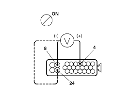
Is the voltage within the specification?

▶Check the HECU connector.If no error is founded, replace the HECU and recheck.

▶Check battery.
2.

CHECK BATTERY.

Measure the voltage between positive(+) and negative(-) terminals of the battery.

Is the voltage below 9.4V?

▶Check and replace the battery.

▶Check circuit for continuity between bettery and HECU.

3.

CHECK CIRCUIT FOR CONTINUITY BETWEEN BATTERY AND HECU.

Check the resistance between terminal 4(+) of the HECU connector and battery positive(+) terminal.

Is the resistance below 1Ω?

▶Repair harness or connector.

▶Check circuit for continuity between the HECU and body ground.

4.

CHECK CIRCUIT FOR CONTINUITY BETWEEN THE HECU AND BODY GROUND.

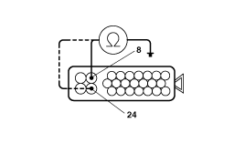
Measure the resistance between terminals 8(-), 24(-) of the HECU connector and the body ground.

Is the resistance below 1Ω?

▶Check and readjust the installing of the body groud.

▶Check voltage beween the HECU connector.

5.

CHECK VOLTAGE BETWEEN THE HECU CONNECTOR.

(1)

Turn the ignition switch ON.

(2)

Measure the voltage between terminals 4(+) and 8(-), 24(-) of the HECU connector.

Is the voltage above 17V?

▶Repair and replace, if necessary, the charging system.

▶Repeat the inspection procedure.

Яндекс.Метрика