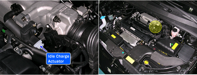

The Idle Charge Actuator (ICA) vlave is installed on the intake manifold and controls the intake airflow that is bypassed around the throttle plate to keep constant engine speed when the throttle vlave is closed. The function of the ICA valve is to maintain idle speed according to various engine loads and conditons, and also to provide additional air during starting. The ICA vlave consists of an opening coil, a closing coil, and a permanent magnet. Based on information from various sensor, the ECM controls both coils by grounding their control circuits. According to the control signals from the ECM, the valve rotor rotates to control the by pass airflow into the engine.
PCM sets DTC P1506 if the PCM detects that the ICAV(OPEN) control circuit is short to battery.
Item | Detecting Condition | Possible Cause |
DTC Strategy | ● Driver stage check | ● Shot to battery in harness ● Contact resistance in connectors ● Faulty ICA valve |
Enable Conditions | ● 10V < Battery voltage < 16V ● 20% < ICA duty < 80% | |
Threshold Value | ● Shot to battery | |
Diagnostic Time | ● 1 sec. |
ICA COIL #1 (OPEN)
Temp.(℃) | Temp.(℉) | ICA Coil #1 (OPEN)(Ω) | Temp.(℃) | Temp.(℉) | ICA Coil #1 (OPEN)(Ω) |
-20 | -4 | 9.2 ~ 10.8 | 40 | 104 | 12.0 ~ 13.6 |
-10 | 14 | 9.7 ~ 11.3 | 50 | 122 | 12.4 ~ 14.0 |
0 | 32 | 10.2 ~ 11.8 | 60 | 140 | 12.9 ~ 14.5 |
10 | 50 | 10.6 ~ 12.2 | 70 | 158 | 13.4 ~ 15.0 |
20 | 68 | 11.1 ~ 12.7 | 80 | 176 | 13.8 ~ 15.4 |
30 | 86 | 11.5 ~ 13.1 | 100 | 212 | 14.7 ~ 16.3 |
ICA COIL #2 (CLOSE)
Temp.(℃) | Temp.(℉) | ICA Coil #2 (CLOSE)(Ω) | Temp.(℃) | Temp.(℉) | ICA Coil #2 (CLOSE)(Ω) |
-20 | -4 | 12.1 ~ 13.7 | 40 | 104 | 15.7 ~ 17.3 |
-10 | 14 | 12.8 ~ 14.4 | 50 | 122 | 16.3 ~ 17.9 |
0 | 32 | 13.4 ~ 15.0 | 60 | 140 | 16.9 ~ 18.5 |
10 | 50 | 14.0 ~ 15.6 | 70 | 158 | 17.4 ~ 19.0 |
20 | 68 | 14.5 ~ 16.1 | 80 | 176 | 18.0 ~ 19.6 |
30 | 86 | 15.1 ~ 16.7 | 100 | 212 | 19.2 ~ 20.8 |
