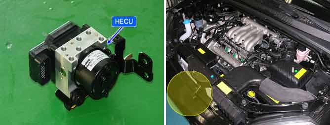

The ABS ECU supplies battery power to the electric motor by way of a motor relay which is controlled by the Electronic Control Unit(ECU). The electric motor pump supplies hydraulic pressure to all wheel brake calipers by operating the piston inside the pump.
The ABS ECU monitors the pump motor relay or fuse open, open or short in motor or motor lock and then sets this code if a malfunction is detected.
Item | Detecting Condition | Possible cause |
DTC Strategy | ● Battery Voltage Monitoring | ● Open or short of power supply circuit (ABS2) ● Faulty HECU |
Case1 (Motor Relay Open or Motor Short to GND) | Detect Mode | ● Outside the ABS control cycle ● Inside the ABS control cycle ● Diagnosis mode |
Enable Conditions | ● If the motor relay is switched ON and motor voltage < (IGN voltage - 4±0.5V) continued for 56msec, the failure is detected. | |
Case2 (Motor Open, Motor Short to BATT) | Detect Mode | ● Initial Check ● Outside the ABS control cycle ● Diagnosis mode ● Failure mode |
Enable Conditions | ● After 1.8sec from the time that motor relay is switched OFF, the motor voltage > 4±0.5V continued for 1.8sec, the failure is detected. | |
Case3 (Motor Lock) | Detect Mode | ● Outside the ABS control cycle |
Enable Conditions | ● After motor relay is switched OFF, motor voltage is measured. If the time which motor voltage > 1±0.1V is less than evaluation time, recheck is performed again for a maximum of three times. When the motor voltage is not normal even on the third recheck, the controller recognizes it as failure. | |
Case4 (Motor Fuse Open) | Detect Mode | ● Initial Check ● Outside the ABS control cycle ● Diagnosis mode ● Failure mode |
Enable Conditions | ● If the motor relay is switched OFF and motor power supply voltage < 4±0.5V continued for 1sec, the failure is detected. | |
Fail Safe | ● The ABS/TCS/ESP functions are inhibited. ● The ABS/TCS/ESP warning lamps are activated and the EBD warning lamp is not activated. ● Motor failure during the ABS control cycle (Case 1, 4) : Inhibit the ABS/TCS/ESP control of front wheels, allow the ABS/TCS/ESP control of rear wheels, and ABS/TCS/ESP warning lamps are switched on at the end of ABS control. |