
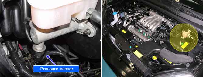
The one pressure sensor ,installed in the master cyclinder, sense the brake oil pressure to judge driver’s brake intention when ESP is operating. If pressure of master cyclinder is applied to pressure sensor, the strain of the piezo element is changed and then the resistance of brige circuit is chanded according to changed strain. Therefore this changed resistance changes output voltage of brige circuit and output voltage changes linerly. The sensor output is a analog signal in proportion to supply voltage, and the HECU recognizes a pressure value according to signal ratio about supply voltage.
Each unfiltered input signal voltage is monitored to be in the range of 0.2V±0.1V< input signal voltage < 4.8V±0.1V. A failure is detected if the output signal value is out of specified range for more than 1s or pressure sensor self test form is against to specification during self test.
Item | Detecting Condition | Possible Cause |
DTC Strategy | ● Voltage Monitoring | ● Open or short of pressure sensor circuit ● Faulty pressure sensor ● Faulty HECU |
Case1 | Detect Mode | ● Initial Check ● Outside the ABS control cycle ● Inside the ABS control cycle ● Diagnosis mode ● Failure mode |
Enable Conditions | ● Vmcp > 4.8±0.1V or Vmcp < 0.2±0.1V continus 1sec. - The monitoring starts 1sec after power up. | |
Case2 | Detect Mode | ● Initial Check |
Enable Conditions | ● When sensor self test form is against to sensor specification. - The monitoring starts 1sec after power up. | |
Case3 | Detect Mode | ● Outside the ABS control cycle ● Inside the ABS control cycle ● Diagnosis mode ● Failure mode |
Enable Conditions | ● While the vehicle is stopped affter driving over 40kph for 3 times, If predefined value of pressure signal is not detected, ECU detect the failure after sensor self test. - The monitoring starts 1sec after power up. | |
Fail Safe | ● Inhibit the ESP control and allow the ABS/EBD/TCS control. Meanwhile, stop checking the ESP switch failure under the ESP control. ● The ESP warning lamps are activated. |