
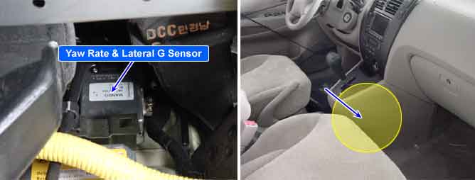
When the vehicle is turning with respect to a vertical axis the yaw rate sensor detects the yaw rate electroniclly by the vibration change of plate fork inside the yaw rate sensor.
If yaw velocity reaches the specific velocity after it detects the vehicle' yawing, the ESP control is reactivated.
The later G sensor senses vehicle's lateral G. A small element inside the sensor is attached to a deflectable leverarm by later G.
Direction and magnitude of lateral G loaded to vehicle can be known with electrostatic capacity changing according to lateral G
It interchanges signals with HECU through extra CAN line which only used for communication between HECU and sensor.
A lateral acceleration reference signal is calculated from the wheel speeds, the steering angle and the yaw rate signals to observe the lateral acceleration sensor signal.
The difference between the reference signal and the sensor signal is evaluated for failure detection. A yaw rate reference signal is calculated from the wheel speeds, the steering angle and the lateral acceleration signals to observe the yaw rate sensor signal.
The difference between the reference signal and the sensor signal, and the gradient of the measured sensor signal is evaluated for the failure detection.
If the difference between estimated value and measured value of the sensor is larger than predefined value for predefined time, the failure is recognized.
Item | Detecting Condition | Possible cause | |
DTC Strategy |
•
Signal monitoring |
•
Faulty Yaw Rate & Lateral G sensor | |
Case1 | Enable Conditions |
•
When the difference between estimated value and measured value of the yaw rate sensor is lager than Predefined value for specific time , ECU detects failure. | |
Case2 | Enable Conditions |
•
When the difference between estimated value and measured value of the lateral G sensor is lager than Predefined value for specific time , ECU detects failure. | |
Case3 | Enable Conditions |
•
Yaw signal is smaller than predefined value when CBIT is transmitted
•
Lateral G signal is smaller than defined value when CBIT is transmitted. ※ CBIT : Commanded Built In Test | |
Case4 | Enable Conditions |
•
In case that Yaw&LG Sensor Fail Flag is detected for defined time | |
Fail Safe |
•
Inhibit the ESP control and allow the ABS/EBD control.
•
The ESP warning lamp is activated. | ||