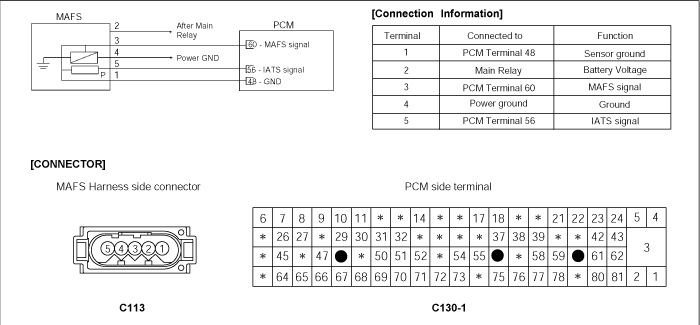
The Mass Air Flow Sensor (MAFS) is located between the air cleaner assembly and the throttle body. The MAFS uses a hot film type sensing element to measure the mass of intake air entering the engine. This hot film type air flow sensor consists of a hot film sensor, housing and metering ducts. Mass air flow rate is measured by detection of heat transfer from a hot film probe. The change in air flow rate causes change in the amount of heat being transferred from the hot film probe surface to the air. A large amount of intake air represents acceleration or high load conditions while a small amount of intake air represents deceleration or idle. The mass of intake air should increase at acceleration and be stable during constant engine speed. The PCM uses this information to determine the injection duration and ignition timing for the desired air/fuel ratio.
The PCM compares the actual measured Mass Air Flow signal to the modeled Mass Air Flow value and sets the DTC P0101 when the difference between these two value is too high or too low with lambda deviation in opposite direction. The PCM illuminates the MIL on the second consecutive driving cycle that the diagnostic runs and fails.
The modeled Mass Air Flow value is determined by engine speed, throttle angle and ICA duty.
Item | Detecting Condition | Possible Cause |
DTC Strategy | ● Compare calculated MAF with MAF signal | ● Dirty air cleaner. ● Oil Cap or Dipstick missing or not installed correctly. ● Air leak in intake system. ● Contact resistance in connectors. ● Faulty MAFS or TPS |
Enable Conditions | ● No relevant failure ● 11 ≤ Battery voltage ≤ 16V ● Lambda control active | |
Threshold Value | ● Calculated MAF - Measured MAF > 300 mg/rev | |
Diagnostic Time | ● 200 revolutions. |
Test Comdition | MAF(V) | MAF(kg/h) | TPS(V) | TPS(㏀) |
Idle | 0.6 ~ 1.0 | 11.66 ~ 19.85 | 0.2 ~ 0.8 | 0.71 ~ 1.38 |
3000 rpm | 1.7 ~ 2.0 | 43.84 ~ 58.79 | - | - |
W.O.T | - | - | 4.3 ~ 4.8 | 0.2 ~ 3.4 |
If any codes relating to TPS or MAFS are stored, do ALL REPAIRS associated with those codes before proceeding with further troubleshooting.
Connect scan tool and select "Diagnostic Trouble Codes(DTCs)" mode
Press F4(DTAL) to select DTC information from the DTCs menu
Confirm that "DTC Readiness Flag" indicates "Complete". If not, drive the vehicle within conditions noted in the freeze frame data or enable conditions
Read "DTC Status" parameter
Is parameter displayed "History(Not Present) fault"?
History (Not Present) fault : DTC occurred but has been cleared.
Present fault : DTC is occurring at present time.
▶ Fault is intermittent caused by poor contact in the sensor's and/or the PCM's connector, which was repaired but PCM memory was not cleared. Thoroughly check connectors for looseness, poor connection, bending, corrosion, contamination, deterioration, or damage. Repair or replace as necessary and go to "Verification of Vehicle Repair" procedure.
▶ Go to next step as below.
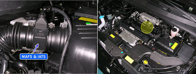
Check air cleaner condition. Is air cleaner clogged with dirt?
▶ Replace air cleaner and go to "Verification of Vehicle Repair" procedure.
▶ Go to "Air Leakage Inspection" procedure
Many malfunctions in the electrical system are caused by poor harness(es) and terminals. Faults can also be caused by interference from other electrical systems, and mechanical or chemical damage.
Thoroughly check connectors for looseness, poor connection, bending, corrosion, contamination, deterioration, or damage.
Has a problem been found?
▶ Repair as necessary and go to "Verification of Vehicle Repair" procedure
▶ Go to "Component Inspection" procedure.
Check Check intake tube, breather hose and MAFS for source of any air leaks. Are there any cracks in intake tube, MAFS or breather hose.
Verify Verify oil cap and dipstick are properly installed and oil cap screwed on completely.
Has a problem been found?
▶ Repair or Replace as necessary and go to "Verification of Vehicle Repair" procedure.
▶ Go to "TPS Inspection" procedure
Ignition "ON" & Engine "OFF".
Install Scantool and monitor the "THROTTLE P.SENSOR(V)" parameter on the Scantool data list.
Specification :
Approx. 0.25~0.80V(Closed throttle Valve)
Approx 4.0~4.4V(Wide Open Throttle)
Is "THROTTLE P.SENSOR(V)" within specification?
▶ Go to "Terminal and Connector Inspection" procedure.
▶ Inspect TP sensor and W/harness and repair or replace as necessary. Go to "Verification of Vehicle Repair" procedure
Engine "ON".
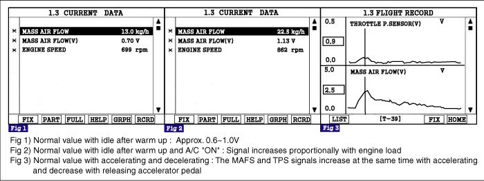
Install Scantool and monitor the "MASS AIR FLOW(V)" parameter on the Scantool data list.
Specification : Approx. 0.6 ~ 1.0V at idle & No load
Is MAF sensor voltage near the specified value?
▶ Check for poor connection between PCM and component: backed out terminal, improper mating, broken locks or poor terminal to wire connection. Repair as necessary and go to "Verification of Vehicle Repair" procedure.
▶ Check MAF for contamination, deterioration, or damage. Substitute with a known-good MAF and check for proper operation. If the problem is corrected, replace MAF and then go to "Verification of Vehicle Repair" procedure.
After a repair, it is essential to verify that the fault has been corrected.
Connect scan tool and select "Diagnostic Trouble Codes(DTCs)" mode
Press F4(DTAL) and confirm that "DTC Readiness Flag" indicates "Complete". If not, drive the vehicle within conditions noted in the freeze frame data or enable conditions.
Read "DTC Status" parameter
Is parameter displayed "History(Not Present) fault"?
▶ System performing to specification at this time. Clear the DTC
▶ Go to the applicable troubleshooting procedure.