4.
Read "DTC Status" parameter.
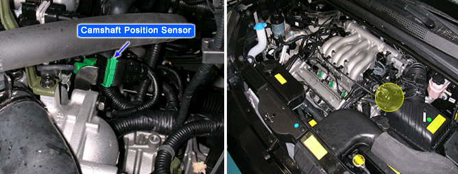
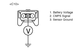
The Camshaft Position Sensor (CMPS) is a sensor that detects the compression TDC of the NO. 1 cylinder. The CMPS consists of a hall type sensor and a target on the end of the intake camshaft. When the target triggers the sensor, the sensor voltage is 5V. If not, the sensor voltage is 0V. These CMPS signal is sent to the ECM and the ECM uses the CMPS signal for synchronizing the firing of sequential fuel injectors.
The ECM monitors the camshaft sensor signal transition position which must change only once per crankshaft revolution. If no camshaft signal is detected while crankshaft signal is detected, the ECM sets DTC P0340.
ITEM | DETECTING CONDITION | POSSIBLE CAUSE |
DTC Strategy | ● Check camshaft signal switching | ● Open or short in signal, ground or power supply circuit ● Contact resistance in connectors ● Misadjust crankshaft and camshaft pulley position ● Faulty CMP sensor |
Enable Conditions | ● No Crankshaft Position Sensor signal error | |
Threshold Value | ● No signal switching | |
Diagnostic Time | ● 80 revolutions |
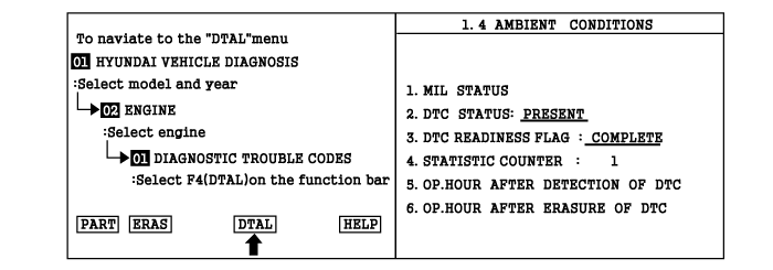
Connect scan tool and select "Diagnostic Trouble Codes(DTCs)" mode.
Press F4(DTAL) to select DTC information from the DTCs menu.
Confirm that "DTC Readiness Flag" indicates "Complete". If not, drive the vehicle within conditions noted in the freeze frame data or enable conditions
Read "DTC Status" parameter.
Is parameter displayed "History(Not Present) fault"?
History (Not Present) fault : DTC occurred but has been cleared.
Present fault : DTC is occurring at present time.

▶ Fault is intermittent caused by poor contact in the sensor's and/or ECM's connector or was repaired and ECM memory was not cleared. Thoroughly check connectors for loose or poor connections, bending, corrosion, contamination, deterioration, or damage. Repair or replace as necessary and go to "Verification of Vehicle Repair" procedure.

▶ Go to next step as below.
Many malfunctions in the electrical system are caused by poor harness(es) and terminals. Faults can also be caused by interference from other electrical systems, and mechanical or chemical damage.
Thoroughly check connectors for looseness, poor connection, bending, corrosion, contamination, deterioration, or damage.
Has a problem been found?
Repair as necessary and go to "Verification of Vehicle Repair" procedure.
Go to "Power Supply Circuit Inspection" procedure.
Ignition "OFF".
Disconnect CMP sensor connector.
Ignition "ON" & Engine "OFF".
Measure voltage between terminal 1 of the sensor harness connector and chassis ground.
Specification : Approx. B+
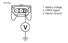
Is voltage within the specification?
▶ Go to "Ground Circuit Inspection" procedure
▶ Check for a open in the power supply circuit between the main relay and the crankshaft position sensor,
Especially check for open or blown 10A sensor fuse refer to "Component Circuit".
Repair as necessary and go to "Verification of Vehicle Repair" procedure.
Ignition "OFF".
Measure resistance between terminals 3 of the sensor harness connector and chassis ground.
Specification : Approx. 0Ω
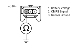
Is resistance within the specification?
▶ Go to "Signal Circuit Inspection" procedure.
▶ Check for an open or short to battery in the ground circuit.
Repair as necessary and go to "Verification of Vehicle Repair" procedure
Check for open in signal harness.
Disconnect ECM connector.
Measure resistance between terminals 2 of the sensor harness connector and 7 of the ECM harness connector.
Specification : Approx. 0Ω
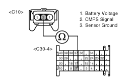
Is resistance within the specification?
▶ Go to next step as below
▶ Repair as necessary and go to "Verification of Vehicle Repair" procedure.
Check for short to ground in signal harness.
Measure resistance between terminal 2 of the sensor harness connector and chassis ground
Specification : Infinite
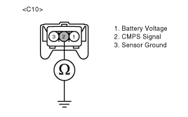
Is resistance within the specification?
▶ Go to next step as below
▶ Repair as necessary and go to "Verification of Vehicle Repair" procedure.
Check for short to power in signal harness.
Ignition "ON" & Engine "OFF"
Measure voltage between terminal 2 of the sensor harness connector and chassis ground
Specification : Approx. 0V
Is voltage within the specification?
▶ Go to "Component Inspection" procedure
▶ Repair as necessary and go to "Verification of Vehicle Repair" procedure.
Start engine and let vehicle idle
Connect scantool and select "Current Data" mode
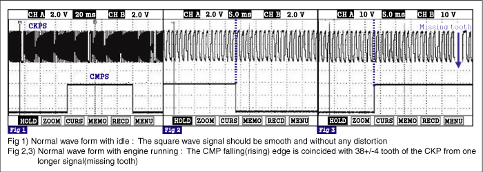
Monitor "CKP T/WHEELS-LO CMP" & "CKP T/WHEELS-HI CMP" parameters on the Scantool data list.
Specification :
"CKP T/WHEELS-LO CMP" : 38 +/- 4 tooth
"CKP T/WHEELS-HI CMP" : 98 +/- 4 tooth
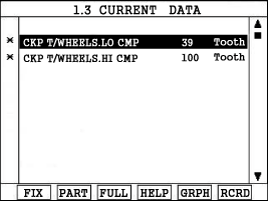
Are "CKP T/WHEELS-LO CMP" & "CKP T/WHEELS-HI CMP" parameters within the specification?
▶ Check for poor connection between ECM and component: backed out terminal, improper mating, broken locks or poor terminal to wire connection. Repair as necessary and go to "Verification Vehicle Repair" procedure .
Remove CKP and calculate air gap.
If fail to synchronize with CMP sensor, readjust timing system and go to next step.
Check CMP sensor for contamination, deterioration, or damage. Substitute with a known-good CMP sensor and check for proper operation. If the problem is corrected, replace CMP sensor and then go to "Verification of Vehicle Repair" procedure.
After a repair, it is essential to verify that the fault has been corrected.
Connect scan tool and select "Diagnostic Trouble Codes(DTCs)" mode.
Press F4(DTAL) and confirm that "DTC Readiness Flag" indicates "Complete". If not, drive the vehicle within conditions noted in the freeze frame data or enable conditions.
Read "DTC Status" parameter.
Is parameter displayed "History(Not Present) fault"?
▶ System performing to specification at this time. Clear the DTC
▶ Go to the applicable troubleshooting procedure.
