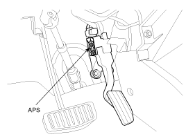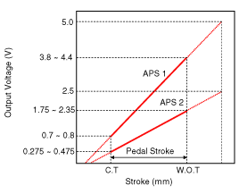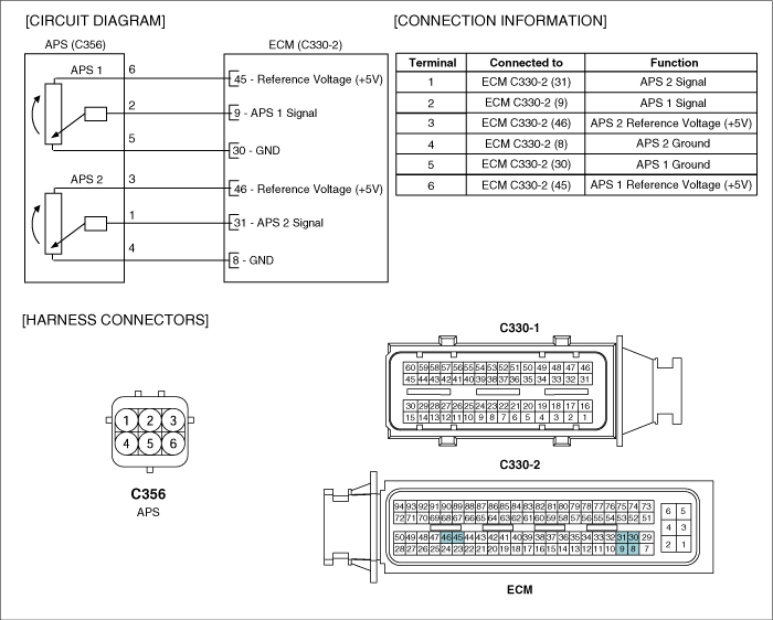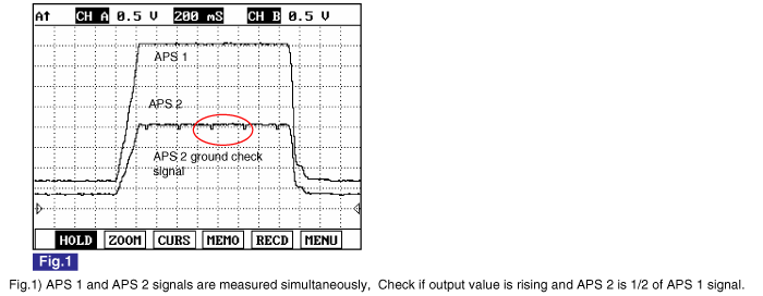
On electronic injection systems, there is no longer a load lever that mechanically controls the fuelling. The flow is caculated by the ECM depending on a number of parameters, including pedal position, which is measured using a potentiometer. The pedal sensor has two potentio-meters whoses slides are mechanically solid. The two potentiometers are supplied from distinct and different power sources so there is built in redundancy of information giving reliable driver's request information. A voltage is generated across the potentiometer in the acceleration position sensor as a function of the accelerator-pedal setting. Using a peogrammed characteristic curve, the pedal's position is then calculated from this voltage.

Test Condition | Output Voltage(V) | |
APS 1 | APS 2 | |
Idle | 0.7 ~ 0.8 | 0.275 ~ 0.475 |
Fully depressed | 3.8 ~ 4.4 | 1.75 ~ 2.35 |
Items | Specification | |
APS 1 | APS 2 | |
Potentiometer Resistance (㏀) | 0.7 ~ 1.3 | 1.4 ~ 2.6 |


Turn ignition switch OFF.
Disconnect the accelerator position sensor connector.
Measure resistance between voltage supply terminal and ground terminal of APS1.
Measure resistance between voltage supply terminal and ground terminal of APS2.
Specification: Refer to "SPECIFICATION".