Thoroughly check connectors for looseness, poor connection, bending, corrosion, contamination, deterioration, or damage.
Has a problem been found?

▶ Repair as necessary and go to "Verification vehicle Repair" procedure.

▶ Go to the next procedure.

Starting engine is possible only in parking and neutral state. Select lever position signal is transmitted to TCM in order to control the select range.
Item | Detecting Condition & Fail Safe | Possible cause |
DTC Strategy | ● - | |
Enable Conditions | ● - | |
Threshold value | ● A situation without the signal of INHIBITOR SW continuance over the 30 seconds | |
Diagnostic Time | ● Over the 30 seconds continuously | |
Fail Safe | ● The system is controlled with the signal just before the detecting condition and after returning, is continuously done with the signal just after reversion. |
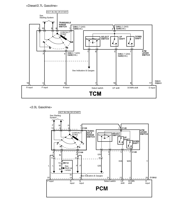
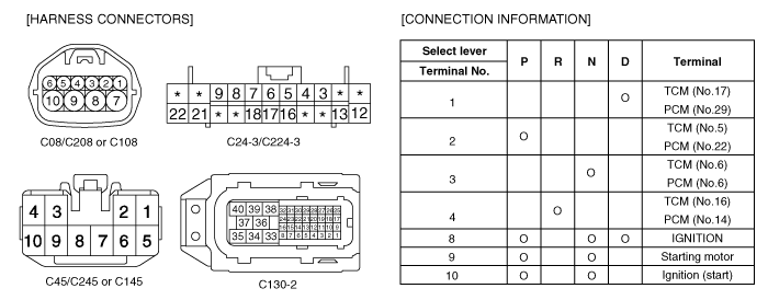
Many malfunctions in the electrical system may be caused from poor harness and terminals. These faults can be caused by interference from other electrical systems and mechanical or chemical damage.
Thoroughly check connectors for looseness, poor connection, bending, corrosion, contamination, deterioration, or damage.
Has a problem been found?

▶ Repair as necessary and go to "Verification vehicle Repair" procedure.

▶ Go to the next procedure.
Power Supply Circuit Inspection
IG KEY ON, ENG OFF
Select lever switch connector: Disconnect
Measure voltage between terminal 8 of select lever switch harness connector and chassis ground
Specification : 11.5V~12.5V
Is voltage display near the specified value?

▶ Check the ground circuit.

▶Inspect open/short circuit between battery (+) and the terminal 2 of the select lever switch connector.
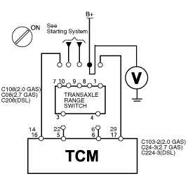
Signal Circuit Inspection
IG KEY ON
TCM(or PCM) connector : Disconnect
Check the voltage signal, changing the select lever.
Measure voltage between signal terminals of select lever switch harness connector and chassis ground.
Specification : 11.5V~12.5V
The signal voltages should be measured in its ranges. If the voltage is measured more than 1 times or is not measured when shifting, inspect the shift control cable and proceed next inspection procedure.
Is voltage display near the specified value?

▶ Proceed next inspection procedure.

▶ Go to the "Component Inspection".
Battery (-) termianl connector: Disconnect
Inhibiter switch connector: Disconnect
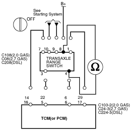
Measure resistance between the range terminals of select switch harness connector and the ones of TCM(or PCM) harness connector.
Specification : Approx. 1Ω below.
Is resistance display near the specified value?

▶ Go to the "Component Inspection".

▶ Repair or replace the signal wire of each range signal line.
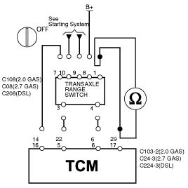
IG KEY OFF, ENG OFF
Disconnect the connectors.
Check the terminals with a transaxle range switch continuity check chart.
Measure resistance between the power supply terminal of the inhibiter switch harness connector and each range terminal.
Specification: refer to 'Connection' in 'Schematic Diagram'.
The signals should be flowed only in its ranges. If not, replace the inhibiter switch.
Does the switch work properly?

▶ Select lever switch OK

▶ Replace the select lever switch.
Condition | Reference | |
*IG KEY : ON ro Engine stop | Select lever : P | P,N |
Select lever : R | R | |
Select lever : N | P,N | |
Select lever : D | D | |