
Disconnect the wire connector from the ETACS module.
Inspect the connector on wire harness side as shown in the below.
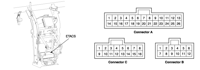
Terminal No. | Connector A | Connector B | Connector C |
1 | Room lamp | Windshield deicer relay | Driver's door lock switch |
2 | B+ | D.R.L | Assist door lock switch |
3 | IGN1 | Tail lamp relay | - |
4 | Alternator (L) | Seat belt indicator | - |
5 | Driver door switch | Key hole illumination | - |
6 | Door switch | Burglar alarm relay | - |
7 | - | Rear defogger relay | - |
8 | - | Power window relay | Door unlock relay |
9 | Windshield deicer switch | Wiper relay | Rear door lock switch |
10 | Front fog lamp switch | Rear fog lamp relay | Auto door unlock |
11 | Head lamp switch | Chime bell | - |
12 | Washer switch | Ground | Hood switch |
13 | Diagnosis | Tailgate switch | |
14 | Signal ground | Hazard lamp relay | |
15 | IGN2 | Start inhibit relay | |
16 | Door warning switch | Door lock relay | |
17 | - | ||
18 | Assist door switch | ||
19 | Tail lamp switch | ||
20 | Code saving | ||
21 | Seat belt switch | ||
22 | Rear defogger switch | ||
23 | Rear fog lamp switch | ||
24 | Intermittent wiper switch | ||
25 | Intermittent wiper volume | ||
26 | Speed sensor |
Pin No. | Input signal name | Test condition | Desired result |
A3 | IGN1 | Ignition switch ON or START | Check for voltage to ground; There should be battery voltage |
A15 | IGN2 | Ignition switch ON | Check for voltage to ground; There should be battery voltage |
A4 | Alternator "L" | Engine start condition | Check for voltage to ground; There should be battery voltage |
A16 | Door warning switch | Key is inserted into the ignition switch | Check for voltage to ground; There should be battery voltage |
A6 | All door switch | One of all doors is opened | Check for continuity to ground; There should be continuity |
A5 | Driver's door switch | Driver's door open | Check for continuity to ground; There should be continuity |
A18 | Assist door switch | Assist door open | Check for continuity to ground; There should be continuity |
C9 | Rear door lock switch | One of rear doors is unlock | Check for continuity to ground; There should be continuity |
C13 | Tailgate switch | Tailgate open | Check for continuity to ground; There should be continuity |
A9 | Windshield deicer switch | Windshield deicer switch ON | Check for continuity to ground; There should be continuity |
C12 | Hood switch | Hood open | Check for continuity to ground; There should be continuity |
A12 | Washer switch | Washer switch ON | Check for continuity to ground; There should be continuity |
A24 | Intermittent wiper switch | INT. wiper switch ON | Check for continuity to ground; There should be continuity |
A25 | Intermittent wiper volume switch | INT. wiper volume switch ON | Resistance should vary from 0Ω to 50kΩ |
A22 | Rear defogger switch | Rear defogger switch ON | Check for continuity to ground; There should be continuity |
A19 | Tail lamp switch | Tail lamp switch ON | Check for continuity to ground; There should be continuity |
A21 | Seat belt switch | Seat belt is unbuckled | Check for continuity to ground; There should be continuity |
A20 | Code saving tool | Code save signal | There should be open at unused |
A2 | Battery (+) | Constant | Check for voltage to ground ; There should be battery voltage |
B12 | Ground | Constant | Check for continuity to ground ; There should be continuity |
C1 | Driver's door lock switch | Driver's door is unlock | Check for continuity to ground ; There should be continuity |
C2 | Assist door lock switch | Assist door is unlock | Check for continuity to ground ; There should be continuity |
A11 | Head lamp switch | Head lamp switch ON | Check for continuity to ground ; There should be continuity |
A26 | Speed sensor | Speed sensor input | Check for voltage to ground; There should be about 0~5V |
A10 | Front fog lamp switch | Front fog lamp switch ON Tail lamp swtich ON | Check for continuity to ground ; There should be continuity |
C10 | Air bag signal | Ignition switch ON | Check for voltage to ground ; There should be about 5V |