CHECK POWER BETWEEN TERMINAL OF HECU CONNECTOR.
Disconnect the connector from the ABS control module, and then turn the ignition switch ON.
Measure the voltage between terminals 4(+) and 8(-) or 24(-) of the HECU connector.
Specification: 9.4~17V
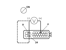
Is the voltage within the specification?
▶Check the HECU connector.If no error is founded, replace the HECU and recheck.
▶Check battery.
CHECK BATTERY.
Measure the voltage between positive(+) and negative(-) terminals of the battery.
Is the voltage below 9.4V?
▶Check and replace the battery.
▶Check circuit for continuity between bettery and HECU.
CHECK CIRCUIT FOR CONTINUITY BETWEEN BATTERY AND HECU.
Check the resistance between terminal 4(+) of the HECU connector and battery positive(+) terminal.
Is the resistance below 1Ω?
▶Repair harness or connector.
▶Check circuit for continuity between the HECU and body ground.
CHECK CIRCUIT FOR CONTINUITY BETWEEN THE HECU AND BODY GROUND.
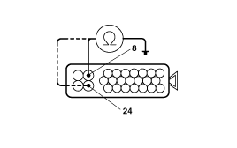
Measure the resistance between terminals 8(-), 24(-) of the HECU connector and the body ground.
Is the resistance below 1Ω?
▶Check and readjust the installing of the body groud.
▶Check voltage beween the HECU connector.
CHECK VOLTAGE BETWEEN THE HECU CONNECTOR.
Turn the ignition switch ON.
Measure the voltage between terminals 4(+) and 8(-), 24(-) of the HECU connector.
Is the voltage above 17V?
▶Repair and replace, if necessary, the charging system.
▶Repeat the inspection procedure.