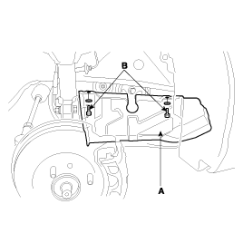
Remove 2bolts(B) and RH side cover(A).
Engine removal is not required for this procedure.
Remove the engine cover.
Remove RH front wheel.
Remove 2bolts(B) and RH side cover(A).

Remove the engine mount bracket.
Set the jack to the engine oil pan.
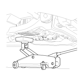
Place wooden block between the jack and engine oil pan.
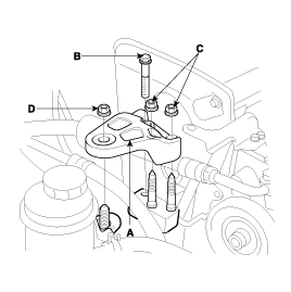
Remove the bolt(B), 3nuts(C, D) and engine mount bracket(A).
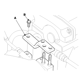
Remove the bolt(B) and stay plate(A).
Temporarily loosen the water pump pulley bolts.
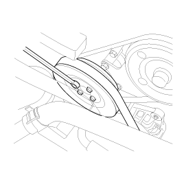
Remove alternator belt. (See EE group - alternator)
Remove air compressor belt. (See HA group - air compressor)
Remove power steering belt. (See ST group - power steering pump)
Remove 4bolts and water pump pulley.
Remove the 4bolts and timing belt upper cover.
Turn the crankshaft pulley, and align its groove with timing mark “T”of the timing belt cover.
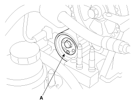
Remove the crankshaft pulley bolt(B) and crankshaft pulley(A).
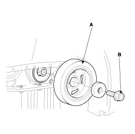
Remove the crankshaft flange(A).
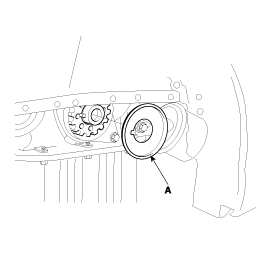
Remove the 5bolts(B) and timing belt lower cover(A).
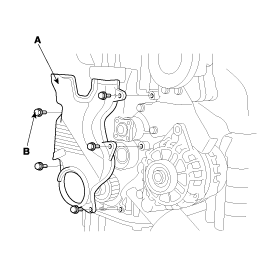
Remove the timing belt tensioner(A) and timing belt(B).
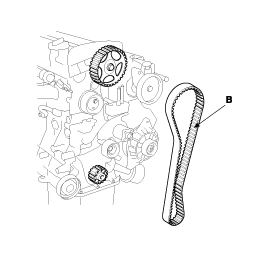
If the timing belt is reused, make an arrow indicating the turning direction to make sure that the belt is reinstalled in the same direction as before.
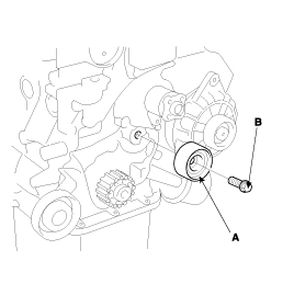
Remove the bolt(B) and timing belt idler(A).
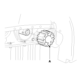
Remove the crankshaft sprocket(A).
Remove the cylinder head cover.
Remove the spark plug cable.
Remove the accelerator cable from the cylinder head cover. (See page EMA - 11)
Remove the PCV(Positive Crankcase ventilation) hose and breather hose. (See page EMA - 11)
Remove the 12bolts and cylinder head cover. (See page EMA - 11)
Remove camshaft sprocket.
Hold the hexagonal head wrench(A) portion of the camshaft with a wrench(B), and remove the bolt and camshaft sprocket(C).
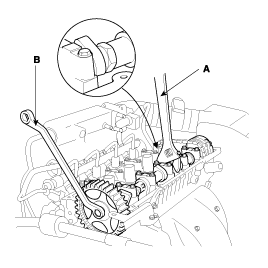
Be careful not to damage the cylinder head and valve lifter with the wrench.
Install the camshaft sprocket and tighten the bolt to the specified torque.
Temporarily install the camshaft sprocket bolt.
Hold the hexagonal head wrench(A) portion of the camshaft with a wrench(B), and tighten the camshaft sprocket(C) bolt.
Tightening torque
Camshaft sprocket bolt
100 ~ 120Nm (1000 ~ 1200kgf.cm, 74 ~ 89lbf.ft)

Install cylinder head cover.
Install cylinder head cover(A) and 12bolts(B).
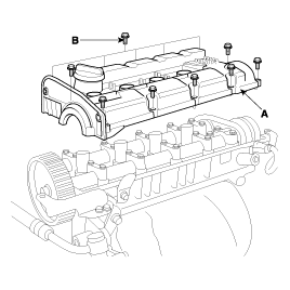
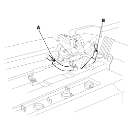
Install the PCV hose(A) and breather hose(B).
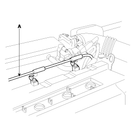
Install the accelerator cable(A) from the cylinder head cover.
Install the spark plug cable.
Install the crankshaft sprocket(A).

Align the timing marks of the camshaft sprocket(A) and crankshaft sprocket(B) with the No.1 piston placed at top dead center and its compression stroke.
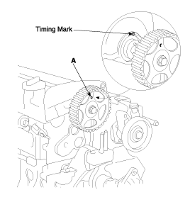
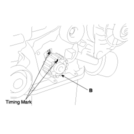
Install the idler pulley(A) and tighten the bolt(B) to the specified torque.
Tightening torque
Idler pulley bolt
43 ~ 55Nm (430 ~ 550kgf.m, 32 ~ 40lbf.ft)

Install the timing belt tensioner loosely enough for the adjuster to rotate. Make sure that the stopper of base is leaning against the lowering sealing cap on the cylinder head.
Belt so as not give slack at each center of shaft. Do as following procedures when installing timing belt.
Crankshaft sprocket (A) → Idler pulley (B) → Camshaft sprocket (C) → timing belt tensioner (D).
(The tensioner can be installed after the timing belt.)
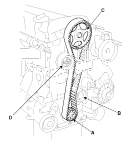
Check the alignment of the timing marks on each sprocket.
Remove the pin fixing the tensioner arm.
Using a hex wrench, turn the adjuster counterclockwise to make the indicator of the arm(A) located at the center of the base notch.
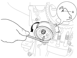
Do not rotate the adjuster clockwise.
It will result in auto tensioner's functional problem.
Tightening tensioner bolt with fixing the indicator not to move.
Tightening torque
Tensioner bolt :
23 ~ 29Nm (230 ~ 290kgf.cm, 17 ~ 21lb-ft)
Turn the crankshaft two revolutions in the operating direction (clockwise) and check that the indicator is in the center of base.
If the indicator is not located at the center of base, slacken the bolt and repeat the abore procedure.
Install the timing belt lower cover(A) with 5 bolts(B).
Tightening torque
Timing belt cover bolt
8 ~ 10Nm (80 ~100kg.cm, 6 ~ 7lbf.ft)

Install the flange and crankshaft pulley(A).
Make sure that crankshaft sprocket pin fits the small hole in the pulley.
Tightening torque
Crankshaft pulley bolt
170 ~ 180Nm (1700 ~ 1800kgf.cm, 125 ~ 133lbf.ft)

Install the timing belt upper cover with 4bolts.
Install the coolant pump pulley with 4bolts.
Install power steering belt. (See ST group - power steering pump)
Install air compressor belt. (See HA group - air comperssor)
Install alternator belt. (See EE group- alternator)
Install the engine mount bracket.
Install the stay plate(A) with bolt(B).
Tightening torque
Stay plate bolt
43 ~ 55Nm (430 ~ 550kgf.cm 32 ~ 40lbf.ft)

Install engine mount bracket(A) with 3nuts and bolt.
Tightening torque
Bolt(B), Nuts(C)
50 ~ 60Nm (500 ~ 600kgf.ft, 37 ~ 48lbf.ft)
Nut(D) : 60 ~ 80Nm (600 ~ 800kgf.m 44 ~ 59lbf.ft)

Install RH side cover(A) with 2bolts(B).

Install RH front wheel.
Install engine cover with 4bolts.
Check the camshaft sproket, crankshaft sprocket, tensioner pulley, and idler pulley for abnormal wear, cracks, or damage. Replace as necessary.
Inspect the tensioner pulley and the idler pulley for easy and smooth rotation and check for play or noise.
Replace as necessary.
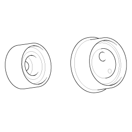
Replace the pulley if there is a grease leak from its bearing.
Check the belt for oil or dust deposits.
Replace, if necessary.
Small deposits should be wiped away with a dry cloth or paper. Do not clean with solvent.
When the engine is overhauled or belt tension adjusted, check the belt carefully. If any of the following flaws are evident, replace the belt.
Do not bend, twist or turn the timing belt inside out.
Do not allow the timing belt to come into contact with oil, water and stem.