COMPONENT LOCATION
GENERAL DESCRIPTION

Comparing with gasoline engine, one of the worst point of diesel engine is that a lot of particle material(PM) are generated after combustion process. In order to decrease the amount of PM, CPF is equipped in EURO-4 diesel engine. CPF is the device which gathers PM with installed filter then burns it up as raising the tempt. inside of CPF above the ignition point of PM. The process which burns up PM is called "CPF regeneration".

※CPF regeneration : When vehicle is in steady speed condition and above normal engine loading condition, if differential pressure between before and after CPF is above the specified pressure, ECM considers that stored soot inside of CPF is excessive. In this condition, exhaust gas tempt. is raised by post injection 1 and 2 to warm CPF up to 550℃~650℃. In this high tempt, soot inside of CPF burns up naturally and this mechanism is called as "CPF regeneration".Most of soot is burned up during regeneration process but a little amount of soot is not burned up and stored inside of CPF continuously. The stored soot decreases the efficiency of CPF slowly. DPS corrects CPF regeneration period and duration as comparing and calculating the differential pressure due to stored soot with the total distance covered.

DTC DESCRIPTION

P1405 is set when regenerating duration lasts more than 600 sec.. This code is often because normal regeneration was not performed as vehicle had driven in city centre.

DTC DETECTING CONDITION

Item

Detecting Condition

Possible Cause

DTC Strategy

Voltage monitoring

Dropped regenerationefficiency

Clogged CPF

Enable Conditions

IG KEY "ON"

Threshold Value

Regenerating duration lasts more than the specified duration

Diagnostic Time

600 sec.

Fail Safe

Fuel cut

NO

Engine check lamp blinks.

EGR Off

NO

Fuel Limit

NO

Check Lamp

BLINK

SPECIFICATION
SCHEMATIC DIAGRAM
SIGNAL WAVEFORM AND DATA
note

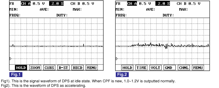
As accelerating, DPS signal output voltage does not vary too much. Even when accelerator pedal is fully depressed, the signal voltage fluctuates just a little bit like "Fig. 2". However, the more CPF is used, the more waveform fluctuates.

MONITOR SCANTOOL DATA
1.

Connect Scantool to Data Link Connector (DLC).

2.

Warm engine up to normal operating temperature.

3.

Turn "OFF" electrical devices and A/C.

4.

Monitor "DIFFERENTIAL PRESSURE" and "PRESSURE PRE CPF" parameter on the scantool.

specification : "DIFFERENTIAL PRESSURE" and "PRESSURE PRE CPF" data must not be too high or low.
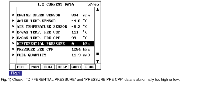
☞ When "DIFFERENTIAL PRESSURE" is too high : Check if excessive soot is accumulated inside of CPF before inspecting DPS related problem.

If needed, perform "CPF SERVICE REGENERATION" to burn the soot inside of CPF and monitor data change.

☞ When "DIFFERENTIAL PRESSURE" is too low : "DIFFERENTIAL PRESSURE" and "PRESSURE PRE CPF" data rises depending on engine load increase and the amount of soot inside of CPF. If differential pressure is not generated or soot is emitted without the rise of "PRESSURE PRE CPF" during excceleration, check CPF component failure.

※The "Scantool Data" shown above is measured at the vehicle with new CPF component. Therfore, data varies depending on CPF used duration and total driven distance.

TERMINAL AND CONNECTOR INSPECTION
1.

Electrical systems consist of a lot of harness and connectors, poor connection of terminals can cause various problems and damge of component.

2.

Perform checking procedure as follows.

(1)

Check damage of harness and terminals : Check terminals for contact resistance, corrosion and deformation.

(2)

Check connecting condition of ECM and component connector : Check terminal seperation, damage of locking device and connecting condition between terminal and wiring.

note

Disconnect the pin which requires checking at male connector and insert it to the terminal at female connector for checking connecting condition. ( after checking, reconnect the pin at correct position. )

3.

Is the problem found?

▶ Repair the trouble causing part and go to "Verification of Vehicle Repair".

▶ Go to "Power Circuit Inspection".

POWER CIRCUIT INSPECTION
1.

IG KEY "OFF", ENGINE "OFF"

2.

Disconnect DPS connector.

3.

IG KEY "ON"

4.

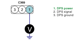
Measure the voltage of DPS connector terminal 1.

Specification : 4.8V~5.1V

5.

Is the measured voltage within the specification?

▶ Go to "Signal Circuit Inspection".

▶ Repair open in power circuit and go to "Verification of Vehicle Repair".

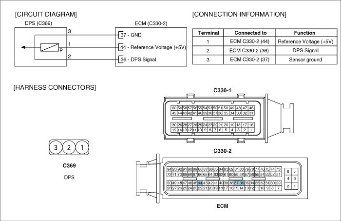
[ Check open between DPS connector terminal 1 and ECM connector(C330-2) terminal 44. ]

SIGNAL CIRCUIT INSPECTION
1.

Check signal circuit voltage

(1)

IG KEY "OFF", ENGINE "OFF"

(2)

Disconnect DPS connector.

(3)

IG KEY "ON"

(4)

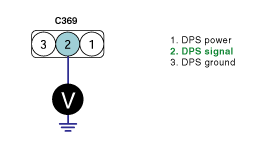
Measure the voltage of DPS connector terminal 2.

Specification : 4.8V~5.1V

(5)

Is the measured voltage within the specification?

▶ Go to "Ground Circuit Inspection".

▶ When voltage is not detected : Go to "2. Check open in signal circuit" as follows.

▶ When high voltage is detected : Repair short to battery and go to "Verification of Vehicle Repair".

2.

Check short to ground in signal circuit

(1)

IG KEY "OFF", ENGINE "OFF"

(2)

Disconnect DPS connector and ECM connector.

(3)

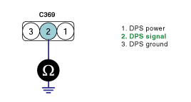
Check continutity between DPS connector terminal 2 and chassis ground.

Specification : Discontinuity (Infinite Ω )

(4)

Is the measured resistance within the specification?

▶ Go to "Component Inspection".

▶ Repair short to ground in signal circuit and go to "Verification of Vehicle Repair".

COMPONENT INSPECTION
1.

DPS visual inspection

(1)

IG KEY "OFF", ENGINE "OFF"

(2)

Disconnect DPS connector.

(3)

Check DPS terminals for corrosion and contamination.

(4)

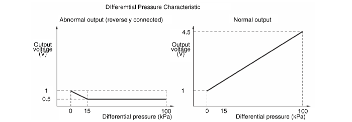
Check (1)connecting condition of DPS and pressure sensing hose, (2)exhaust gas pressure leakate, (3)miss connection of pressure sensing hose (reverse connection) is detected.

(5)

Is DPS related problem detected?

▶ If needed, replace DPS or pressure sensing hose and go to "Verification of Vehicle Repair".

▶ Go to "2. Monitor DPS signal waveform" as follows.

2.

Monitor DPS signal waveform

(1)

IG KEY "ON", ENGINE "OFF"

(2)

Connect DPS connector.

(3)

Connect oscilloscope to DPS connector terminal 2.

(4)

After warming engine up, monitor the waveform at idle and during acceleration.

Specification : Refer to "Signal Waveform & Data" of "General Information".

(5)

Is DPS signal waveform is similar to the waveform of "Signal Waveform & Data"?

▶ Go to "Verification of Vehicle Repair".

▶ Replace DPS and go to "Verification of Vehicle Repair".

VERIFICATION OF VEHICLE REPAIR

After a repair, it is essential to verify that the fault is corrected.

1.

After connecting Scantool select "DIAGNOSTIC TROUBLE CODES(DTCs)" mode.

2.

Clear recorded DTC using Scantool.

3.

Drive the vehicle within DTC "Enable conditions" in "General information".

4.

After selecting "DIAGNOSTIC TROUBLE CODES(DTCs)" mode and check if DTC is recorded again.

5.

Are any DTCs recorded ?

▶ Go to the DTC guide of recorded NO. in Scantool.

▶ System operates within specification.

Яндекс.Метрика