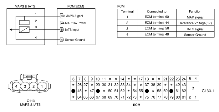
The amount of intake air flow must be inputted to ECM in order to determine the fuel injection quantity. MAPS(Manifold Absolute Pressure) calculates the amount of air indirectly as measuring the pressure inside of intake manifold. This mechanism is also called Speed-Density Type. MAPS transfers analog output signal which is proportional to the change of intake manifold pressure, then, with this signal and RPM, ECM calculates the amount of intake air flow. MAPS is mounted on surge tank to measure the pressure inside of intake manifold, and it consists of a piezo electric element and hybrid IC which amplifies output signal from the element. A piezo electric element is a sort of a diaphragm using piezo electric effect. One side of the diaphragm is surrounded with vacuum chamber while intake pressure is applied to the other side. Thus, signals are outputted by the transformation of diagphragm according to the change of pressure inside of intake manifold.
ECM compares the MAPS output and calculated MAPS value while enable condition is met. If the acutal MAP value is higher than Maximum threshold or lower than Minimum threshold for a pre-determined time, ECM determines that a fault exists and a DTC is stored.
Item | Detecting Condition | Possible Cause |
DTC Strategy | ● Plausability check | ● Dirty air cleaner. ● Oil Cap or Dipstick missing or not installed correctly. ● Air leak in intake system ● Contact resistance in connectors. ● Faulty MAFS or TPS |
Enable Conditions | ● No relevant failure ● 10 V≤ Battery voltage ≤ 16V ● Lambda close loop control activated | |
Threshold Value | ● Difference between model pressure and measured pressure > 280hpa ● Deviation value of fuel trim control > 20% or < -20% | |
Diagnostic Time | ● 200 revolutions. | |
Mil On Condition | ● 2 Driving Cycles |
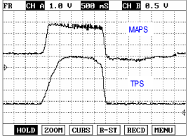
As often as possible, the MAPS signal should be compared with the TPS signal. Check whether the MAPS and TPS signals increase at the same time when accelerating. During acceleration, the MAPS output voltage increases; during deceleration, the MAPS output voltage decreases.
If any codes relating to TPS or MAFS are stored, do ALL REPAIRS associated with those codes before proceeding with further troubleshooting.
Connect scan tool and select "Diagnostic Trouble Codes(DTCs)" mode
Press F4(DTAL) to select DTC information from the DTCs menu
Confirm that "DTC Readiness Flag" indicates "Complete". If not, drive the vehicle within conditions noted in the freeze frame data or enable conditions
Read "DTC Status" parameter
Is parameter displayed "History(Not Present) fault"?
History (Not Present) fault : DTC occurred but has been cleared.
Present fault : DTC is occurring at present time.
![]() | ▶ Fault is intermittent caused by poor contact in the sensor's and/or ECM's connector or was repaired and ECM memory was not cleared. Thoroughly check connectors for looseness, poor connection, bending, corrosion, contamination, deterioration, or damage. Repair or replace as necessary and then go to "Verification of Vehicle Repair" procedure. |
![]() | ▶ Go to next step as below. |
Many malfunctions in the electrical system are caused by poor harness(es) and terminals. Faults can also be caused by interference from other electrical systems, and mechanical or chemical damage.
Thoroughly check connectors for looseness, poor connection, bending, corrosion, contamination, deterioration, or damage.
Has a problem been found?
![]() | ▶ Repair as necessary and go to "Verification of Vehicle Repair" procedure. |
![]() | ▶ Go to next step as below |
IG "OFF".
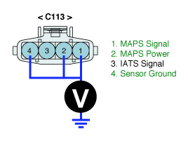
Disconnect MAPS connector.
IG "ON" & ENG "OFF"
Measure voltage between terminal 1, 2,4 of MAPS harness connector and chassis ground.
Specification : Terminal 1 : Approx. 5V
Terminal 2 : Approx. 5V
Terminal 4 : Below 0V
Is the measured voltage within specification ?
![]() | ▶ Go to "Component Inspection " procedure. |
![]() | ▶ Repair or replace as necessary and then, go to "Verification of Vehicle Repair" procedure. |
Check MAPS performance.
IG "OFF".
Connnect CH A probe to terminal 1 of MAPS and CH B probe to terminal 1 of TPS connector.
Warm up the engine to normal operating temperature.
Measure signal waveform of MAPS and TPS together by stepping on and off the accellerator pedal.
Pressure (kPa) | Approx. 20 | Approx. 35 | Approx. 60 | Approx. 95 | Approx. 101 |
Voltage(V) | Approx. 0.7~0.8 | Approx. 1.3~1.4 | Approx. 2.3~2.4 | Approx. 3.7~3.8 | Approx. 3.9~4.1 |
Is the measured signal waveform(Comparison response of TPS with MAPS) O.K ?
![]() | ▶ Thoroughly check connectors for looseness, poor connection, bending, corrosion, contamination, deterioration, or damage. Repair or replace as necessary and go to "Verification of Vehicle Repair" procedure. |
![]() | ▶ Substitute with a known - good MAPS and check for proper operation. If the problem is corrected, replace MAPS and go to "Verification of Vehicle Repair" procedure. |
After a repair, it is essential to verify that the fault has been corrected.
Connect scan tool and select "Diagnostic Trouble Codes(DTCs)" mode
Press F4(DTAL) and confirm that "DTC Readiness Flag" indicates "Complete". If not, drive the vehicle within conditions noted in the freeze frame data or enable conditions
Read "DTC Status" parameter
Is parameter displayed "History(Not Present) fault"?
![]() | ▶ System performing to specification at this time. Clear the DTC |
![]() | ▶ Go to the applicable troubleshooting procedure. |