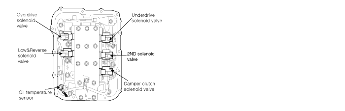
The Automatic Transmission changes the gear position of the transmission by utilizing a combination of Clutches and Brakes, which are controlled by solenoid valves.
DTC DESCRIPTION
The TCM checks the Low and Reverse Control Signal by monitoring the feedback signal from the solenoid valve drive circuit.
DTC DETECTING CONDITION
Item
Detecting Condition & Fail Safe
Possible cause
DTC Strategy
● Check voltage range
※ TORQUE CONVERTER(DAMPER) CLUTCH : TCC
● Open or short in circuit
● Faulty LR SOLENOID VALVE
● Faulty PCM/TCM
Enable Conditions
● Solenoid status Either solid On or OFF
● Voltage of Battery >10V
Threshold value
● Voltage <3V
Diagnostic Time
● more than 320 ms
Fail Safe
● Locked in 3 rd gear.(Control relay off)
MONITOR SCANTOOL DATA
1.
Connect scantool to data link connector(DLC)
2.
Engine "ON".
3.
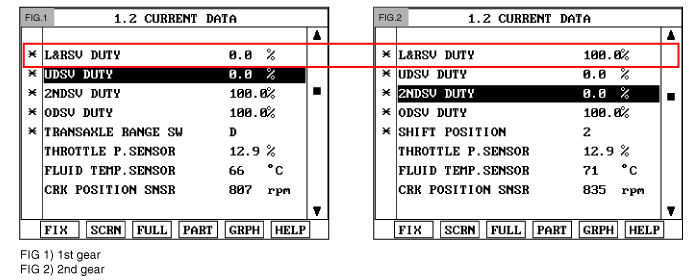
Monitor the "LR SOL. VALVE" parameter on the scantool
4.
Select "R" range and monitor "LR SOLENOID DUTY" is 0%
Specification: 1st → 0%, 2nd → 100%
Does "LR SOLENOID DUTY " follow the referance data?
▶ Fault is intermittent caused by poor contact in the sensor's and/or TCM(PCM)'s connector or was repaired and TCM(PCM) memory was not cleared. Throughly check connectors for looseness, poor connection, bending, corrosion, contamination, deterioration or
▶ Go to "W/Harness Inspection " procedure
TERMINAL & CONNECTOR INSPECTION
1.
Many malfunctions in the electrical system are caused by poor harness and terminals. Faults can also be caused by interference from other electrical systems, and mechanical or chemical damage.
2.
Thoroughly check connectors for looseness, poor connection, bending, corrosion, contamination, deterioration, or damage.
Has a problem been found?
▶ Repair as necessary and then go to "Verification of Vehicle Repair" procedure
▶ Go to "Power Circuit Inspection" procedure
POWER SUPPLY CIRCUIT INSPECTION
1.
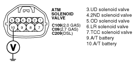
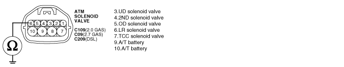
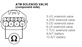
Disconnect "A/T SOLENOID VALVE" connector.
2.
Measure voltage between teminal"10" of the sensor harness connector and chassis ground.
3.
Turn ignition switch OFF → ON
Specification: 12V is measured only for approx. 0.5sec
Is voltage within specifications?
▶ Go to "Signal circuit inspection" procedure
▶ Check that A/T-20A Fuse in engine room junction is installed or not blown.
▶ Check for open in harness. Repair as necessary and Go to "Verification Vehicle Repair" procedure
SIGNAL CIRCUIT INSPECTION
1.
Check signal circuit open inspection
(1)
Ignition "OFF".
(2)
Disconnect "A/T SOLENOID VALVE" connector and "PCM/TCM" connector
(3)
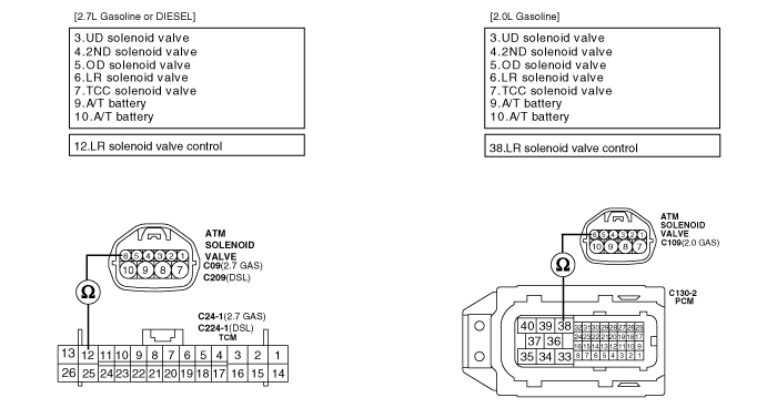
Measure resistance between terminal "6" of the ATM SOLENOID VALVE harness connector and terminal "12" of the PCM/TCM harness connector
Specification: approx. 0 Ω
Is resistance within specifications?
▶ Go to "Check signal circuit short Inspection" procedure
▶ Check for open in harness. Repair as necessary and Go to "Verification Vehicle Repair" procedure
2.
Check signal circuit short inspection
(1)
Ignition "OFF".
(2)
Disconnect "A/T SOLENOID VALVE" connector and "PCM/TCM" connector
(3)
Measure resistance between terminal "6" of the ATM SOLENOID VALVE harness and chassis ground.
Specification: Infinite
Is resistance within specifications?
▶ Go to "Component Inspection" procedure
▶ Check for short to ground in harness. Repair as necessary and Go to "Verification Vehicle Repair" procedure
COMPONENT INSPECTION
1.
CHECK SOLENOID VELVE
(1)
Ignition "OFF".
(2)
Disconnect "A/T SOLENOID VALVE" connector
(3)
Measure resistance between terminal "6" and terminal "10" of the ATM SOLENOID VALVE harness connector
Specification: Approximately 2.7~3.4 Ω (20°C)
Is resistance within specification?
▶ Go to "CHECK PCM/TCM" as below
▶ Replace LR SOLENOID VALVE as necessary and go to "Verification Vehicle Repair" procedure
2.
CHECK PCM/TCM
(1)
Connect scantool to data link connector(DLC)
(2)
Ignition "ON" & Engine "OFF".
(3)
Select A/T Solenoide valve Actuator test and Operate Actuator test.
Can you hear operating sound for LR SOLENOID VALVE Actuator Testing Function ?
▶ Go to "Verification Vehicle Repair" procedure
▶ Replace PCM/TCM as necessary and Go to "Verificaiton Vehicle Repair" procedure
ACTUATOR TEST CONDITION
A.
IG SWITCH ON
B.
TRANSAXLE RANGE SWITCH is normal
C.
P RANGE
D.
Vehicle Speed 0km/h
E.
Throttle position sensor < 1V
F.
IDLE SWITCH ON
G.
ENGINE RPM 0
VERIFICATION OF VEHICLE REPAIR
After a repair, it is essential to verify that the fault has been corrected.
1.
Connect scan tool and select "Diagnostic Trouble Codes(DTCs)" mode.
2.
Using a scantool, Clear DTC.
3.
Operate the vehicle within DTC Enable conditions in General information.
Are any DTCs present ?
▶ Go to the applicable troubleshooting procedure.
▶ System performing to specification at this time.
SPECIFICATION
Solenoid Valve for Pressure Control
● Sensor type : Normal open 3-way
● Operating temperature : -22~266°F(-30°C∼130°C)
● Frequency :
- LR, 2ND, UD, OD, RED : 61.27Hz (at the ATF temp. -20°C above)