Side airbag deployment will be determined by SRSCM that will detect satellite sensor impact signal upon side crash, irrespective to seat belt condition.
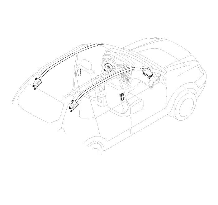
The supplemental restraint system (SRS) is designed to supplement the seat belt to help reduce the risk or severity of injury to the driver and passenger by activating and deploying the driver, passenger, side airbag and belt pre-tensioner in certain frontal or side collisions.
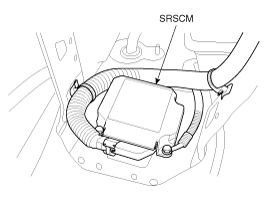
The SRS (Airbag) consists of : a driver side airbag module located in the center of the steering wheel, which contains the folded cushion and an inflator unit ; a passenger side airbag module located in the passenger side crash pad contains the folded cushion assembled with inflator unit ; Side airbag modules located in the driver and passenger seat contain the folded cushion and an inflator unit. SRSCM located on the floor under the heater core which monitors the system, an accelerometer which senses the vehicle deceleration, a spring interconnection (clock spring) located within the steering column ; system wiring and wiring connector; and a knee bolster located under the steering column. The impact sensing function of the SRSCM is carried out by electronic accelerometer that continuously measure the vehicle's acceleration and delivers a corresponding signal through amplifying and filtering circuity to the microprocessor.
The SRS airbag system consists of electrical and electronic. Be cautious in the airbag parts.
SRSCM will detect front impact with inside sensor, and side impact with side impact sensor, detect airbag deployment request signal, and determine airbag module deployment.
DC/DC converter: DC/DC converter in power supply unit includes up/down transformer converter, and provide ignition voltage for 2 front airbag ignition circuits and inside operation voltage. If inside operation voltage is below critical value setting, it will perform re-setting.
Safety sensor: Safety sensor is located in airbag ignition circuit. Safety sensor will operate airbag circuit at any deployment condition and release airbag circuit safely at normal driving condition. Safety sensor is a double contact electro-mechanical switch that will close detecting deceleration above certain criteria.
Back up power supply: SRSCM has separate back up power supply, that will supply deployment energy instantly in low voltage condition or upon power failure by front crash.
Self diagnosis: SRSCM will constantly monitor current SRS operation status and detect system failure during vehicle power supply is on, system failure may be checked with trouble codes using scan too. (Hi-Scan)
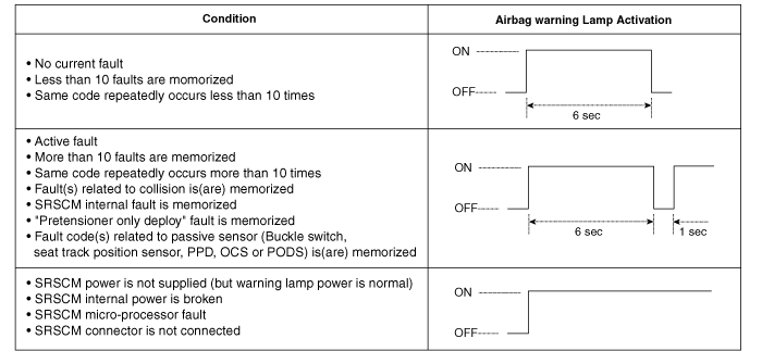
Airbag warning lamp on: Upon detecting error, the module will transmit signal to SRSCM indicator lamp located at cluster. MIL lamp will indicate driver SRS error. Upon ignition key on, SRS lamp will blink 7 times to indicate operation.
Trouble code registration: Upon error occurrence in system, SRSCM will store DTC corresponding to the error. DTC can be cleared only by Hi-Scan.
Self diagnostic connector: Data stored in SRSCM memory will be output to Hi-Scan or other external output devices through connector located below driver seat crash pad.
Once airbag is deployed, SRSCM should not be used again but replaced.
SRSCM will determine whether passenger has put on seat belt using built-in switch signal in seat belt buckle, and deploy front seat airbag at each set crash speed.
Side airbag deployment will be determined by SRSCM that will detect satellite sensor impact signal upon side crash, irrespective to seat belt condition.


PIN NO. | FUNCTION | INPUT/OUTPUT |
1 | Driver airbag, High (+) | Output |
2 | Driver airbag, Low (-) | Output |
3 | Passenger airbag, High (+) | Output |
4 | Passenger airbag, Low (-) | Output |
5 | - | - |
6 | - | - |
7 | - | - |
8 | - | - |
9 | Driver side airbag, High (+) | Output |
10 | Driver side airbag, Low (-) | Output |
11 | Passenger side airbag, High (+) | Output |
12 | Passenger side airbag, Low (-) | Output |
13 | Driver curtain airbag, High (+) | Output |
14 | Driver curtain airbag, Low (-) | Output |
15 | Passenger curtain airbag, High (+) | Output |
16 | Passenger curtain airbag, Low (-) | Output |
17 | - | - |
18 | - | - |
19 | - | - |
20 | - | - |
21 | Driver belt pretensioner, High (+) | Output |
22 | Driver belt pretensioner, Low (-) | Output |
23 | Battery supply | Input |
24 ~ 25 | Shorting bar | - |
26 | - | - |
27 | Crash output | Output |
28 | Driver front impact sensor, High (+) | Output |
29 | Driver front impact sensor, Low (-) | Output |
30 | Passenger front impact sensor, High (+) | Output |
31 | Passenger front impact sensor, Low (-) | Output |
32 | - | - |
33 | - | - |
34 | Driver side impact sensor, High (+) | Output |
35 | Driver side impact sensor, Low (-) | Output |
36 | Passenger side impact sensor, High (+) | Output |
37 | Passenger side impact sensor, Low (-) | Output |
38 ~ 45 | - | - |
46 | Passenger belt pretensioner, High (+) | Output |
47 | Passenger belt pretensioner, Low (-) | Output |
48 | K-diagnostic line | Input/Output |
49 | Ground | Input |
50 | Warning lamp | Output |
The driver airbag (DAB), the passenger airbag (PAB), the side airbag (SAB), and the curtain airbag (CAB) modules that consist of the inflator (ignitor) and the cushion, the ignition unit (cracker, ignitor charger, gas) is integrated into the inflator. Upon front or side crash of intensity enabling SRSCM sensor operation, current will flow through the ignitor circuit. Current will flow into the inflator and activate the ignition material in the inflator to deploy the airbag.
The clock spring (coil spring) consists of two current carrying coils. It is attached between the steering column and the steering wheel. It allows rotation of the steering wheel while maintaining continuous contact of the deployment loop through the inflator module.
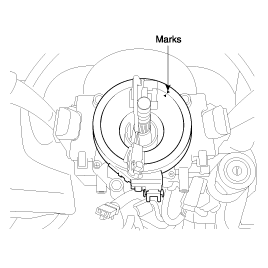
The steering wheel must be fitted correctly to the steering column with the clock spring at the neutral position, otherwise cable disconnection and other troubles may result.
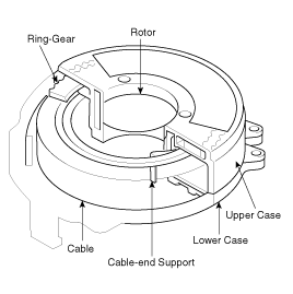
The system includes ring gear (90 teeth) located at upper case, transparent cover installed at rotor with screw, and gear (80 teeth) interlocked with ring gear and driven by prominent part of the cover. Upper case is installed on the steering column at fixed position. Rotor is connected with steering column and always rotate with steering wheel. Gear is always interlocked with ring gear by prominent part of the cover. Rotor and prominent part of the cover will rotate together.
Therefore, gear will rotate in reverse direction to rotor by 10 teeth difference with the ring gear. On the gear, R2, R1, NEUTRAL, L1 and L2 marks are embedded on every tenth teeth. Matching marks are on the upper case. Clock spring mark should match with gear's NEUTRAL mark when the vehicle is in straight forward position. Gear's R mark indicates rotor rotation clockwise and L counterclockwise. In order to center again, turn the steering wheel clockwise to the end, and thereafter turn counterclockwise about 3 revolution to match the mark.
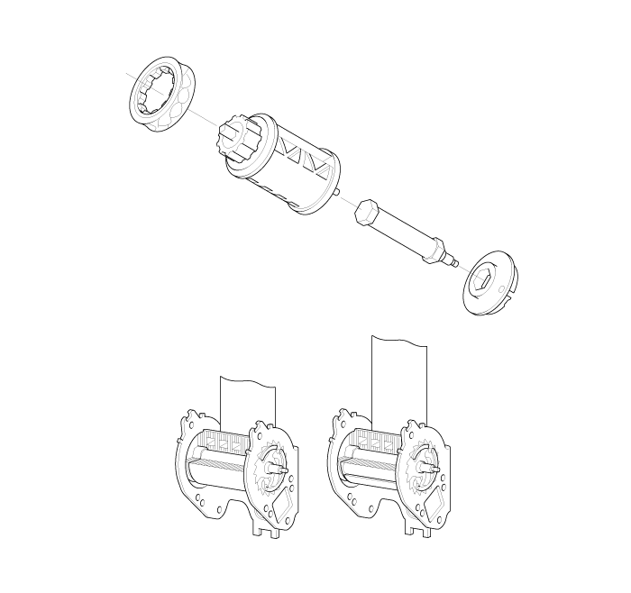
This system is designed to protect the occupants from moving forward by transmitting a signal from SRSCM to the ignition system (gas generator) which in built is the pre-tensioner belt. When the ignition system explodes, then the spindle will turn in reverse direction to keep the belt from waving and hold the passengers.
The Load Limiter is designed to restrain the passenger by the seat belt from moving forward in case of an accident. In order to protect the passenger from injury, the torsion bar installed in the seat belt will be deformed when pressure between chest and the belt reaches 500kg/cm2 or more, so that it reduces the impact by releasing the seat belt.
The SRS harness is wrapped in yellow tube to be discriminated from other system harness. And the shorting bar is included inside the wiring connectors of DAB, PAB, SAB and BPT inflator side. The shorting bar shorts the current flow DAB, PAB, SAB and BPT module circuit when the connectors are disconnected. The circuits to the inflator module are shorted in this way to help prevent unwanted deployment of the airbag when serving the airbag module.
There are certain fault conditions in which the SRSCM (SRS Control Module) cannot function and thus cannot control the operation of the lamp. In these cases, the lamp is directly activated by appropriate circuitry that operates independently of the SRSCM, as follow.
Loss of ignition voltage supply to the SRSCM : Lamp turned on continuously.
Loss of internal operating voltage : Lamp turned on continuously.
SRSCM malfunctioning : Lamp turned on continuously.
SRSCM not connected : Lamp turned on through shorting bar in wiring harness connector.
