3.
Check the center support bearing for excessives play or rattle and rubber for rent. If the center support has excessive play or rattle and rubber has rent, replace the propeller shaft assembly.
Shift the transmission to Neutral.
Raise the vehicle off the ground, and support it witj safety stands in the proper locations.
Check the center support bearing for excessives play or rattle and rubber for rent. If the center support has excessive play or rattle and rubber has rent, replace the propeller shaft assembly.
Check the VJ joint boots for damage and deterioration. If the boots are damaged or deteriored. replace the propeller shaft assembly.
Check the VJ joints for excessive play or rattle.
If the universal joints have excessive play or rattle, replace the propeller shaft assembly.
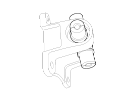
Install a dial indicator with its needle on the center of front propeller shaft or rear propeller shaft.
Turn the other propeller shaft slowly and check the runout. Repear this procedure for the other propeller shaft.
Front Propeller Shaft Runout : 0.3mm (0.012in.)
Rear Porpeller Shaft Runout : 0.3mm (0.012in.)
If the runout on either propeller shaft exceeds the service limit, replace the propeller shaft assembly.
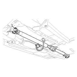
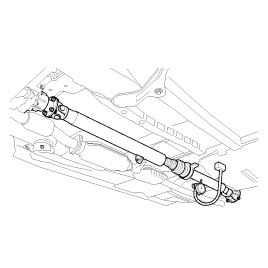
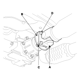
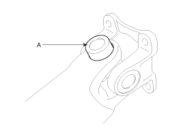
After making a match mark(C) on the rubber coupling(A) and rear differential companion(B), remove the propeler shaft mounting bolts(D).
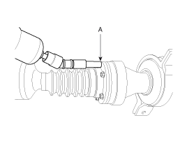
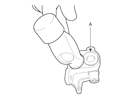
Remove the center bearing bracket mounting bolts(A).
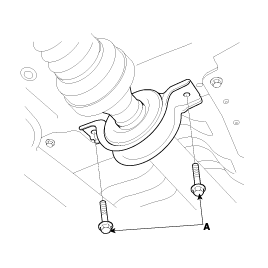
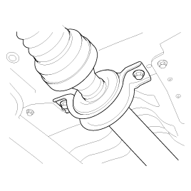
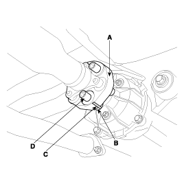
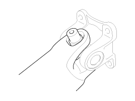
After making a match mark(C) on the flange yoke(A) and transaxle companion(B), remove the propeller shaft mounting bolts(D).
If a grease leak is shown around the nuiversal joint, be sure to put grease in the universal joint through the nipple enough until grease come out of the universal joint.
Installation is the reverse of the removal procedures
Install according to match mark of transaxle companion (or rear differential companion) and propeller shaft.
Items | Nm | Kgf.cm | lbf.ft |
Front propeller shaft mounting bolt | 50 ~ 60 | 500 ~ 600 | 36.9 ~ 44.3 |
Center bearing bracket mounting bolt | 40 ~ 50 | 400 ~ 500 | 29.5 ~ 36.9 |
Rear propeller shaft mounting bolt | 100 ~ 120 | 1000 ~ 1200 | 73.8 ~ 88.5 |
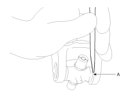
After marking the alignment point on front or rear, loosen 6EA bolts on the C.V. Joint(A).
The alignment point assembles in the direction to marked reassemble.
It is to minimize the change of balance.
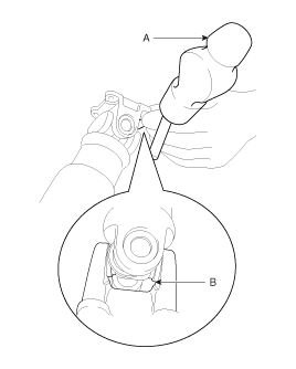
After fixing the pipe on the circle vise, loosen the nut by using impact(A) (26mm).
When you fix the pipe, you should use the circle vise or cleat.
It is to prevent the crush of pipe.
Disassemble the key pliers as shown in the illustration.
Disassemble the flange(A) by using a tool.
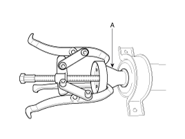
After disassembling by using the key pliers, disassemble the flange(A).
Before disassembling flange, mark the alignment point.
It is to assemble with alignment, when you reassemble flange.
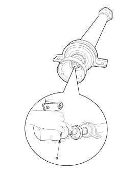
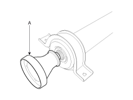
If center bearing do not fall, lightly hit the center bearing as shown in the illustration. Then, center bearing(A) is disassembly.
When you hit strongly, appear the abrasion in the shape of the screw thread.
Installation is the reverse order of removal.
After marking alignment point on flange yoke and tube yoke, disassemble snap ring(B) on tube yoke.
The alignment point assembles in the direction on marked reassemble.
It is to minimize the change of balance.
Disassemble the case(A) by using hammer as shown in the illustration.
Do not hit too strongly with hammer.
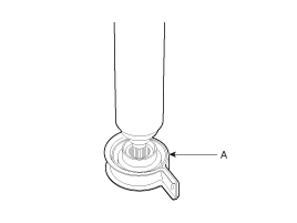
Disassemble snap ring(A) on the yoke.
Disassemble the case(A) by using hammer as shown in the illustration.
Do not hit too strongly with hammer.
Installation is the reverse order of removal.
