Description | Specifications | Limit |
General |
Type | In-line, Double Overhead Camshaft | |
Number of cylinder | 4 | |
Bore | 82mm (3.228in) | |
Stroke | 93.5mm (3.681in.) | |
Total displacement | 1975cc (120.52cu.in.) | |
Compression ratio | 10.1 | |
Firing order | 1-3-4-2 | |
Valve timing |
Intake valve | | |
Opens | ATDC 11° ~ BTDC 29° | |
Closes | ABDC 59° ~ 19° | |
Exhaust | | |
Opens | BBDC 42° | |
Closes | ATDC 6° | |
Valve |
Valve length | | |
Intake | 114.34mm (4.5016in.) | |
Exhaust | 116.8mm (4.598in.) | |
Stem O.D. | | |
Intake | 5.965 ~ 5.98mm (0.2348 ~ 0.2354in.) | |
Exhaust | 5.950 ~ 5.965mm (0.2343 ~ 0.2348in.) | |
Face angle thickness of valve head (Margin) |
Intake | 1.15mm (0.0452in.) | 0.8mm (0.031in.) |
Exhaust | 1.35mm (0.0531in.) | 1.0mm (0.039in.) |
Valve stem to valve guide clearance |
Intake | 0.02 ~ 0.05mm (0.0008 ~ 0.0019in.) | 0.10mm (0.0039in.) |
Exhaust | 0.035 ~ 0.065mm (0.0014 ~ 0.0026in.) | 0.13mm (0.0051in.) |
Valve guide |
Installed dimension O.D | | |
Intake | 46mm (1.811in.) | |
Exhaust | 54.5mm (2.146in.) | |
Service oversize | 0.05, 0.25, 0.50mm(0.002, 0.010, 0.020in.) oversize | |
Valve seat |
Width of seat contact | | |
Intake | 1.1 ~ 1.5mm (0.043 ~ 0.059in.) | |
Exhaust | 1.3 ~ 1.7mm (0.051 ~ 0.066in.) | |
Seat angle | 45° | |
Oversize | 0.3, 0.6mm (0.012, 0.024in.) oversize | |
Valve spring |
Free length | 48.86mm (1.9236in.) | |
Load | 18.3kg/39mm (40.31lb/1.535in.) | |
Installed height | 39mm (1.5354in.) | |
Squarences | 1.5° or less | |
Valve clearance |
Cold (20°C[68°F]) | | |
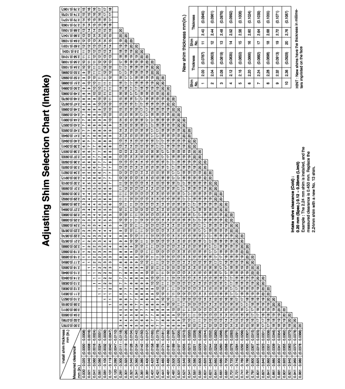
Intake | 0.20mm (0.0079in.) | 0.12 ~ 0.28mm(0.0047 ~ 0.0110in.) |
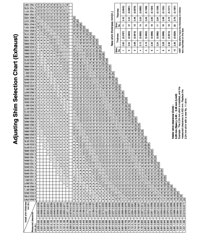
Exhaust | 0.28mm (0.0110 in,) | 0.20 ~ 0.38mm(0.0079 ~ 0.0150in.) |
Hot (80°C[176°F]) : only for reference | | |
Intake | 0.29mm (0.0014in.) | |
Exhaust | 0.34mm (0.0134in.) | |
Cylinder head |
Flatness of gasket surface | Max. 0.03mm (0.0012in.) | 0.06mm (0.0024in.) |
Flatness of manifold mounting surface | Max. 0.15mm (0.0059in.) | 0.03mm (0.0012in.) |
Oversize rework dimensions of valve seat hole | | |
Intake | | |
0.3mm (0.012in.) O.S. | 33.300 ~ 33.325mm (1.3110 ~ 1.3120in.) | |
0.6mm (0.024in.) O.S. | 33.600 ~ 33.625mm (1.3228 ~ 1.3238in.) | |
Exhaust | | |
0.3mm (0.012in.) O.S. | 28.800 ~ 28.821mm (1.1338 ~ 1.1346in.) | |
0.6mm (0.024in.) O.S. | 29.100 ~ 29.121mm (1.1456 ~ 1.1465in.) | |
Oversize rework dimensions of valve guide hole (both intake and exhaust) | | |
0.05mm (0.002in.) O.S | 11.05 ~ 11.068mm (0.435 ~ 0.4357in.) | |
0.25mm (0.010in.) O.S | 11.25 ~ 11.268mm (0.443 ~ 0.4436in.) | |
0.50mm (0.020in.) O.S | 11.50 ~ 11.518mm (0.453 ~ 0.4535in.) | |
Cylinder block |
Cylinder bore | 82.00 ~ 82.03mm (3.2283 ~ 3.2295in.) | |
Out-of-round and taper of cylinder bore | Less than 0.01mm (0.0004in.) | |
Clearance with piston (To set limits to new parts) | 0.02 ~ 0.04mm (0.0008 ~ 0.0016in.) | |
Piston |
O.D (To set limits to new parts) | 81.97 ~ 82.00mm (3.2271 ~ 3.2283in.) | |
Service oversize | 0.25, 0.50mm (0.010, 0.020in.) oversize | |
Piston ring |
Side clearance | | |
No.1 | 0.04 ~ 0.08mm (0.0015 ~ 0.0031in.) | 0.1mm (0.004in.) |
No.2 | 0.03 ~ 0.07mm (0.0012 ~ 0.0027in.) | |
End gap | | |
No.1 | 0.23 ~ 0.38mm (0.0090 ~ 0.0149in.) | 1mm (0.039in.) |
No.2 | 0.33 ~ 0.48mm (0.0130 ~ 0.0189in.) | 1mm (0.039in.) |
Oil ring side rail | 0.20 ~ 0.60mm (0.0078 ~ 0.0236in.) | 1mm (0.039in.) |
Service oversize | 0.25, 0.50mm(0.010, 0.020in.) oversize | |
Connecting rod |
Bend | 0.05mm (0.0020in.) or less | |
Twist | 0.1mm (0.004in.) or less | 0.4mm (0.0157in.) |
Connecting rod big end to crankshaft side clearance | 0.100 ~ 0.250mm (0.0039 ~ 0.010in.) | |
Connecting rod bearing |
Oil clearance (To seat limits to new parts) | 0.024 ~ 0.044mm (0.0009 ~ 0.0017in.) | |
Undersize | 0.25, 0.50, 0.75mm (0.01, 0.02, 0.03in.) | |
Camshaft |
Cam height | | |
Intake | 44.618mm (1.7566in.) | 44.518mm (1.7527in.) |
Exhaust | 44.518mm (1.7527in.) | 44.418mm (1.7487in.) |
Jourmal O.D. | 28mm (1.1023in.) | 0.1mm (0.0039in.) |
Bearing oil clearance | 0.02 ~ 0.061mm (0.0008 ~ 0.0024in.) | |
End play | 0.1 ~ 0.2mm (0.004 ~ 0.008in.) | |
Crankshaft |
Pin O.D. | 45mm (1.77in.) | |
Journal O.D. | 57mm (2.244in.) | |
Bend | 0.03mm (0.0012in.) or less | |
Out-of-round, taper of journal and pin | 0.01mm (0.0004in.) or less | 0.030mm (0.0012in.) |
End play | 0.06 ~ 0.260mm (0.0023 ~ 0.010in.) | |
Undersize rework dimension of pin | | |
0.25mm (0.010in.) | 44.725 ~ 44.740mm (1.7608 ~ 1.7614in.) | |
0.50mm (0.020in.) | 44.475 ~ 44.490mm (1.7509 ~ 1.7516in.) | |
0.75mm (0.030in.) | 44.225 ~ 44.240mm (1.7411 ~ 1.7417in.) | |
Undersize rework dimension of journal | | |
0.25mm (0.010in.) | 56.727 ~ 56.742mm (2.2333 ~ 2.2339in.) | |
0.50mm (0.020in.) | 56.477 ~ 56.492mm (2.2235 ~ 2.2240in.) | |
0.75mm (0.030in.) | 56.227 ~ 56.242mm (2.2136 ~ 2.2142in.) | |
Crankshaft bearing |
Oil clearance | 0.028 ~ 0.046mm (0.0011 ~ 0.0018in.) | |
Flywheel |
Runout | 0.1mm (0.0039in.) | 0.13mm (0.0051in.) |
Cooling method | Water-cooled, pressurized. Forced circulation with electrical fan | |
Coolant |
Quantity | 6 liter (6.3U.S qts, 5.2lmp. qts) | |
Radiator |
Type | Pressurized corrugated fin type | |
Radiator cap |
Main valve opening pressure | 83 ~ 110kpa (12 ~ 16psi, 0.83 ~ 1.1kg/cm²) | |
Vacuum valve opening pressure | -7kpa (-100psi, -0.07kg/cm²) or less | |
Thermostat |
Type | Wax pellet type with jiggle valve | |
Valve opening temperature | 82°C (177°F) | |
Full-opening temperature | 95°C (201°F) | |
Coolant pump |
Drive belt |
Type | V-ribbed belt | |
Engine coolant temperature sensor |
Type | Heat-sensitive thermistor type | |
Resistance | 2.31 ~ 2.59KΩ at 20°C (68°F) | |
Oil pump |
Clearance between outer circumference and front case. | 0.120 ~ 0.185mm (0.0049 ~ 0.0073in.) | |
Front case tip clearance | | |
Side clearance | 0.025 ~ 0.069mm (0.0009 ~ 0.0027in.) | |
Inner gear | | |
Outer gear | 0.04 ~ 0.085mm (0.0016 ~ 0.0033in.) | |
Engine oil pressure at 1500 RPM | 0.04 ~ 0.09mm (0.0016 ~ 0.0035in.) | |
[Oil temperature is 90 to 110°C (194 to 230°F)] | 245KPa (2.5kg/cm², 35.5psi) | |
Relief spring |
Free height | 43.8mm (1.725in.) | |
Load | 3.7kg at 40.1mm (3.15lb/1.578in.) | |
Air cleaner |
Type | Dry type | |
Element | Unwoven cloth type | |
Exhaust pipe |
Muffler | Expansion resonance type | |
Suspension system | Rubber hangers | |
Item | Nm | kgf.cm | lbf.ft |
Cylinder Block |
Front engine support bracket bolt and nut | 35 ~ 50 | 350 ~ 500 | 25 ~ 37 |
Front roll stopper bracket bolt | 70 ~ 90 | 700 ~ 900 | 51 ~ 65 |
Rear roll stopper bracket bolt | 70 ~ 90 | 700 ~ 900 | 51 ~ 65 |
Rear engine stopper bracket bolt | 35 ~ 50 | 350 ~ 500 | 25 ~ 37 |
Engine Mounting |
Right mounting insulator (large) nut | 90 ~ 110 | 900 ~ 1100 | 65 ~ 80 |
Right mounting insulator (small) nut | 45 ~ 60 | 450 ~ 600 | 33 ~ 44 |
Right mounting bracket to engine nuts and bolts | 50 ~ 65 | 500 ~ 650 | 36 ~ 48 |
Transmission mount insulator nut | 90 ~ 110 | 900 ~ 1100 | 65 ~ 80 |
Transmission insulator bracket to side member bolt | 40 ~ 50 | 400 ~ 500 | 30 ~ 36 |
Rear roll stopper insulator nut | 50 ~ 65 | 500 ~ 650 | 36 ~ 48 |
Rear roll stopper bracket to center member bolts | 40 ~ 50 | 400 ~ 500 | 30 ~ 36 |
Front roll stopper insulator nut | 50 ~ 65 | 500 ~ 650 | 36 ~ 48 |
Front roll stopper bracket to center member bolts. | 40 ~ 50 | 400 ~ 500 | 30 ~ 36 |
Main Moving |
Connecting rod cap nut | 50 ~ 53 | 500 ~ 530 | 36 ~ 39 |
Crankshaft bearing cap bolt | (27.5~31.4) + (60~65°) | (280~320) + (60~65°) | (20.3~23.1) + (60~65°) |
Fly wheel M/T bolt | 120 ~ 130 | 1200 ~ 1300 | 88 ~ 95 |
Drive plate A/T bolt | 120 ~ 130 | 1200 ~ 1300 | 88 ~ 95 |
Engine cover | 4 ~ 6 | 40 ~ 60 | 3 ~ 4 |
Heat protector | 15 ~ 20 | 150 ~ 200 | 11 ~15 |
Water pipe bracket bolts | 12 ~ 15 | 120 ~ 150 | 9 ~ 11 |
Cooling system |
Alternator support bolt and nut | 20 ~ 25 | 200 ~ 250 | 14 ~ 18 |
Alternator lock bolt | 12 ~ 15 | 120 ~ 150 | 9 ~ 11 |
Alternator brance mounting bolt | 20 ~ 27 | 200 ~ 270 | 15 ~ 20 |
Coolant pump pulley bolts | 8 ~ 10 | 80 ~ 100 | 6 ~ 7 |
Coolant pump bolts | 20 ~ 27 | 200 ~ 270 | 14 ~ 19 |
Coolant temperature sensor | 20 ~ 40 | 200 ~ 400 | 15 ~ 30 |
Coolant inlet fitting nuts | 15 ~ 20 | 150 ~ 200 | 11 ~ 14 |
Thermostat housing bolts and nuts | 15 ~ 20 | 150 ~ 200 | 11 ~ 14 |
Lubrication system |
Oil filter | 12 ~ 16 | 120 ~ 160 | 9 ~ 12 |
Oil pan bolts | 10 ~ 12 | 100 ~ 120 | 7 ~ 9 |
Oil pan drain plug (Aluminum) | 39.2 ~ 49.0 | 400 ~ 500 | 28.9 ~ 36.2 |
Oil pan drain plug (Steel) | 34.3 ~ 44.1 | 350 ~ 450 | 25.3 ~ 32.5 |
Oil screen bolts | 15 ~ 22 | 150 ~ 220 | 11 ~16 |
Oil pressure switch | 13 ~ 15 | 130 ~ 150 | 9.7 ~11 |
Intake and Exhaust system |
Air cleaner body mounting bolts | 8~ 10 | 80 ~ 100 | 6 ~ 7 |
Resonator mounting bolts | 4 ~ 6 | 40 ~ 60 | 3 ~ 4 |
Intake manifold to cylinder head nuts and bolts | 16 ~ 23 | 160 ~ 230 | 12 ~ 17 |
Intake manifold stay to cylinder block bolts | 18 ~ 25 | 180 ~ 250 | 13 ~ 18 |
Throttle body to surge tank nuts | 15 ~ 20 | 150 ~ 200 | 11 ~ 14 |
Exhaust manifold to cylinder head nuts | 43 ~ 55 | 430 ~ 550 | 32 ~ 40 |
Exhaust manifold cover to exhaust manifold bolts | 15 ~ 20 | 150 ~ 200 | 11 ~ 14 |
Oxygen sensor to front muffler | 50 ~ 60 | 500 ~ 600 | 36 ~ 43 |
Oxygen sensor to exhaust manifold | 50 ~ 60 | 500 ~ 600 | 36 ~ 43 |
Front exhaust pipe to exhaust manifold nuts | 30 ~ 40 | 300 ~ 400 | 22 ~ 29 |
Front exhaust pipe bracket bolts | 30 ~ 40 | 300 ~ 400 | 22 ~ 29 |
Front exhaust pipe to catalytic converter bolts | 40 ~ 60 | 400 ~ 600 | 29 ~ 43 |
Main muffler hanger support bracket bolts | 10 ~ 15 | 100 ~ 150 | 7 ~ 11 |
Cylinder head |
Cylinder head bolts - M10 | (22.6~26.5) + (60~65°) + (60~65°) | (230~270) + (60~65°) + (60~65°) | (16.6~19.5) + (60~65°) + (60~65°) |
Cylinder head bolts - M12 | (27.5~31.4) + (60~65°) + (60~65°) | (280~320) + (60~65°) + (60~65°) | (20.3~23.1) + (60~65°) + (60~65°) |
Intake manifold nuts | 18 ~ 25 | 180 ~ 250 | 13 ~ 18 |
Exhaust manifold nuts | 43 ~ 55 | 430 ~ 550 | 32 ~ 41 |
Cylinder head cover bolts | 8 ~ 10 | 80 ~ 100 | 6 ~ 7 |
Camshaft bearing cap bolts | 14 ~ 15 | 140 ~ 150 | 10 ~ 11 |
Oil control valve bolt | 10 ~ 12 | 100 ~ 120 | 7.3 ~ 8.8 |
OCV Filter | 41 ~ 51 | 410 ~ 510 | 30 ~ 37.6 |
CVVT unit to exhaust camshaft bolt | 66 ~ 78 | 660 ~ 780 | 48.7~ 57.5 |
Rear plate bolts | 8 ~ 10 | 80 ~ 100 | 6 ~ 7 |
Timing Belt |
Crankshaft pulley bolt | 170 ~ 180 | 1700 ~ 1800 | 125 ~ 133 |
Camshaft sprocket bolt | 100 ~ 120 | 1000 ~ 1200 | 74 ~ 89 |
Timing belt auto tensioner bolt | 23 ~ 29 | 230 ~ 290 | 17 ~ 21 |
Timing belt cover bolts | 8 ~ 10 | 80 ~ 100 | 6 ~ 7 |
Front case bolts | 20 ~ 27 | 200 ~ 270 | 14 ~ 20 |
Timing belt idler bolt | 43 ~ 55 | 430 ~ 550 | 31 ~ 40 |
