
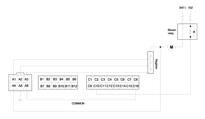
When the blower is turned ON, blower relay becomes turned ON and battery voltage is supplied to the blower motor upper part. The current determined by the supplied battery voltage, blower motor, and register ground runs to GND through the blower motor and the selected blower single resister.
Symptoms | Possible causes | How to check |
Blower malfunction | Short wire of register | |
Blower wind is discharged despite switching OFF | Open circuit of blower switch | With switch OFF, check the connection between each terminal and GND/COMMON terminal |
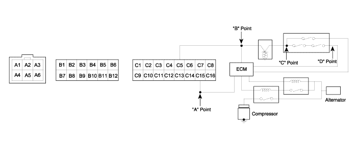
For A/CON output, blower must be basically operated. When blower speed 1 is selected, blower relay is turned ON and voltage is supplied to point "A".
When the supplied voltage at point "A" is entered into control connector C15 and at this moment when A/CON switch is turned ON, voltage is supplied to connector C5 at 9V or more.
Thermistor value determines whether the input power at point "B" is supplied to point "C".
The state of ON/OFF of triple switch determines whether the input power at point "C" is supplied to point "D".
Finally when the voltage is supplied to point "D", engine ECU determines whether A/CON and CONDENSER FAN turned ON/OFF.
Symptoms | Possible causes | How to check |
Wind of A/CON isn't discharged into in-car despite switching OFF of A/CON | Signal output error of A/CON | With switch OFF of A/CON, and measure voltage of connector C5 as shown in the above figure. If the voltage is 9V or more, check the triple switch, ENG ECU, and wires. |
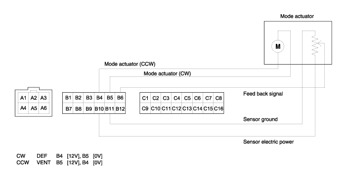
As shown in the above figure, in adjusting mode switch from VENT to DEF, 12V is outputted from connector B4, 0V is supplied for B5 and mode motor works in direction of DEF. In adjusting mode switch from DEF to VENT, 12V is outputted from connector B5, 0V is supplied for B4 and mode motor works in direction of VENT. When mode actuator has to move to a certain location for its automatic control, mode feedback signal terminal moves equally in mode actuator and informs controller of location of mode actuator through mode connector B6. Comparing original value with the inputted value, it works until they are same.
Symptoms | Causes | How to check |
Mode actuator running error | Power supply error in mode actuator | After altering VENT to DEF, measure voltage of connector B4, and after altering DEF to VENT, measure voltage of connector B5. If both of them are 9V and more, check mode actuator and peripheral wiring state and if one or both of them are 9V and less, its cause is internal failure of control. |
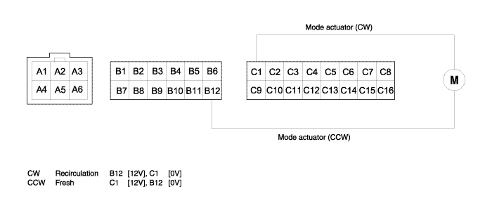
In turning on IG and selecting indoor mode with indoor switch, 12V is outputted from connector B12, 0V is supplied for C1 and motor works in direction of indoor. In selecting outdoor mode with indoor switch, 12V is outputted from connector C1, 0V is supplied for B12 and motor works in direction of outdoor.
Symptoms | Causes | How to check |
Indoor mode running error | Power supply error in actuator | Separate connector linked with actuator, select indoor mode with indoor switch and measure voltage of connector B12. If 9V and more, check actuator or wiring state and if 9V and less, check the inside of controller. |
Outdoor mode running error | Power supply error in actuator | Select outdoor mode in the above method and measure voltage of connector C1. If 9V and more, check actuator or wiring state and if 9V and less, check the inside of controller. |
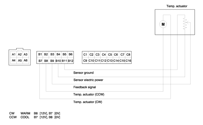
As shown in the above figure, in adjusting temp. switch from WARM to COOL, 12V is outputted from temp. connector B7, 0V is supplied for B8 and temp. motor works in direction of COOL. In adjusting temp. switch from COOL to WARM, 12V is outputted from temp. connector B8, 0V is supplied for B7 and temp. motor works in direction of WARM. When temp. actuator has to move to a certain location for its automatic control, temp. feedback signal terminal moves equally in temp. actuator and informs controller of location of temp. actuator through temp. connector B9. Comparing original value with the inputted value, it works until they are same
Symptoms | Causes | How to check |
Temp actuator running error | Power supply error in temp actuator | After altering COOL to WARM, measure voltage of B7, and after altering WARM to COOL, measure voltage of B8. If Both of them are 9V and more, check temp actuator and peripheral wiring state and if one or both of them are 9V and less, its cause is internal failure of control. |