
Alternator output and power demand of all electrical loads and systems must be matched to each other as ideally as possible so that the entire system is reliable and trouble-free in operation. The PCM monitors alternator output deviation from the signal of the FR terminal of the alternator when the engine is running.
PCM sets DTC P0626 if the PCM detects output duty signal higher than the possible range of a properly operating alternator.
Item | Detecting Condition | Possible Cause |
DTC Strategy |
•
Electrical Check | 1. Open or short to ground in harness 2. Faulty charging system |
Enable Conditions |
•
Time after ignition ON > 0.1sec.
•
Engine speed=0
•
No main relay error | |
Threshold Value |
•
Alternator load > 35% | |
Diagnostic Time |
•
1sec. | |
MIL On Condition |
•
- |
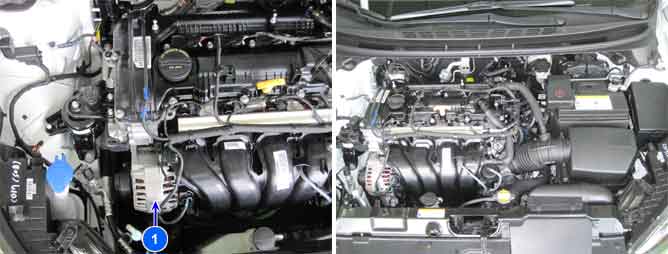
Fig.1) Idle Status
Fig.2) Electrical Load (Head Lamp and Defrost are ON
Duty(+) from FR terminal is increased if electrical loads are ON (Head Lamp and Defrost are ON)
PCM controls generation of alternator with duty from FR terminal when electrical Loads turn on