2.
Check sensor data as below.
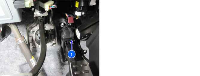
The Electronic Throttle Control(ETC) system is made of the components throttle body, Throttle Position Sensor(TPS) 1&2 and Accelerator Position Sensor(APS)1&2.The APS is mounted in the accelerator pedal to detect the opening angle of the accelerator pedal. It has 2 sensors to detect the accelerator position and a malfunction of the accelerator position sensor. The PCM judges the current opening angle of the accelerator pedal from APS1&2, and the PCM controls the throttle motor based on these signals.
PCM sets DTC P2138 if the PCM detects output voltage of the APS1 is not proportion to APS2.
Item | Detecting Condition | Possible Cause |
DTC Strategy |
•
Plausibility check | 1. Poor connection or damaged harness 2. APS1 3. APS2 |
Enable Conditions |
•
No relevant failure
•
APS1 >1.0V or APS2 >0.55V | |
Threshold Value |
•
Ratio check between pedal sensor channel 1and 2 | |
Diagnostic Time |
•
0.35sec. | |
MIL On Condition |
•
Immediate | |
Limp-Home |
•
Forced limited power mode : The PCM limits opening angle of the throttle valve to max. 50% and engine torque to a certain pre-determined value.
•
The PCM selects the current opening angle of the throttle valve from minimum value of APS1 and APS2. |
IG key ON.
Check sensor data as below.
Data Analysis
Condition | GDS Sensor Data | ||
APS 1 | APS 2 | ||
IG Key "ON & Engine "OFF" | Output voltages of APS1 and APS2 are in proportion to accelerating. APS2 output voltage is half of APS1 output voltage. | ||
Release a pedal fully | 0.58~0.93V | 0.29~0.38 | |
Depress a pedal fully | 3.85~4.35V | 1.93~2.18V | |
Is data in accordance with "Data Anaysis"?
 | ▶ Check for poor connection between PCM and component: backed out terminal, improper mating, broken locks or poor terminal to wire connection. Repair as necessary and go to "Verification of Vehicle Repair" procedure. |
 | ▶ Go to next procedure. |
