1.
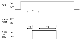
Under IGN2 = ON, wiper LOW relay is turned ON after T2 from Washer switch ON if washer switch is ON for T1 and wiper LOW relay is turned OFF after T3.
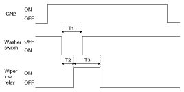
T1:0.06s~0.2s, T2:0.3s ±0.1s, T3:0.7s ±0.1s
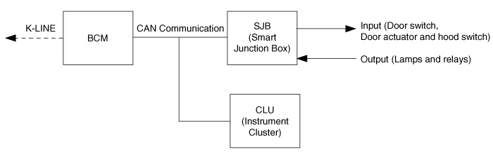
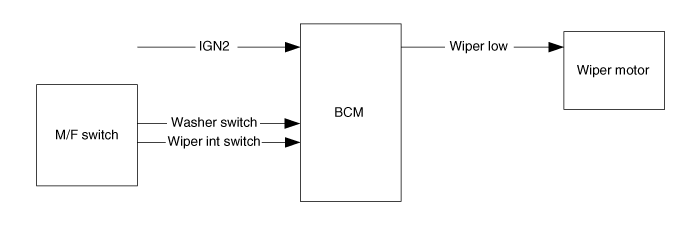
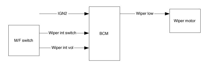
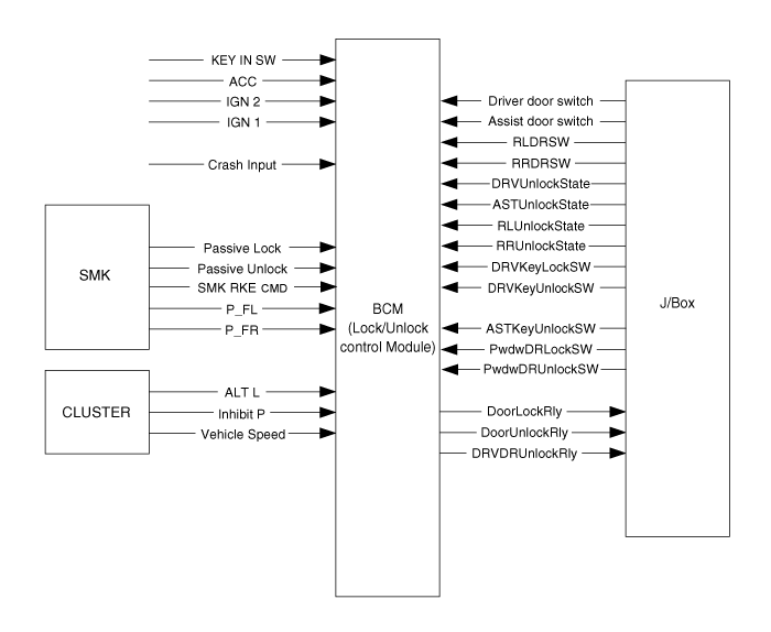
Body control module receives various input switch signals controlling time and alarm functions for the intermittent wiper timer, washer timer, rear defogger timer, seat belts warning, central door lock, ignition key reminder, power window, door warning, tail lamp, crash door unlock, ignition key hole illumination, rear fog lamp control and keyless entry & burglar alarm.
BCM, SJB(Smart Junction Box) and CLU(Instrument Cluster) are connected by CAN line.
The nearest module with input switch or actuator receives the input data to reduce the wiring and then send input data to the others which need them via CAN lines.
In case of sending output, it is used to CAN communication, not wiring.
SJB can also control relays and IPS.
So Each module allots the current data and actuation data.
Under IGN2 = ON, wiper LOW relay is turned ON after T2 from Washer switch ON if washer switch is ON for T1 and wiper LOW relay is turned OFF after T3.
T1:0.06s~0.2s, T2:0.3s ±0.1s, T3:0.7s ±0.1s
Under IGN2 switch ON, wiper LOW relay is turned ON after T2 from Washer switch ON if washer switch is ON for at least T1, and wiper LOW relay is turned OFF after T3 from the moment that Washer switch is turned OFF.
T1:0.2s(MIN), T2:0.3s ±0.1s
T3:2.5s~3.8s(2~3 Turn)
Operation in Item (2) is performed if Washer switch is ON for at least T1 during WIPER operation with Wiper int switch. Operation in Item (1) is performed if Washer switch is ON for T6.
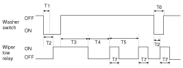
T1:0.2s(MIN) , T2:0.3s ±0.1s
T3:2.5s~3.8s(2~3 Turn), T4:T5 - 0.7s
T5:INT TIME, T6:0.06s ~0.2s, T7:0.7s ±0.1s
Operation is cancelled in case of IGN OFF during T3.
Give priority to WASHER interlocking WIPER than Speed sensing INT WIPER function.
Washer switch signal input shall be ignored at start-up (IGN1 ON & IGN2 OFF states).
Switch ON time includes chattering time
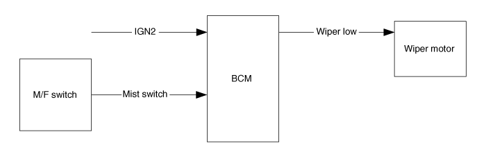
Function Description
In case of IGN2 On (IGN2 ON), if turning on the Wiper Mist switch(Wiper Mist switch On), then Wiper is controlled, by switch on time. Mist operation does not work at Wiper Washer.
Mist Switch On Time (TMist) | Action |
TMist < 0sec | No action |
0sec ≤ TMist < 0.7sec | After “Mist Out Delay Time”, turn on the Wiper Low Output for “One Wiping” Time (the remaining motor operation to reach wiper park position is done by electrical wiring) |
0.7sec ≤ TMist | After “Mist Out Delay Time”, turn on the Wiper Low Output and after Mist switch off, Wiper Low Output is Off immediately (the remaining motor operation to reach wiper park position is done by electrical wiring) |
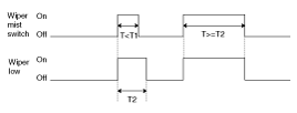
T1 : One Wiping, T2 : Mist One Time
Under IGN2 switch ON, Wiper LOW relay is turned ON immediately from Mist switch ON if Mist switch ON for more than T1, Wiper LOW relay is turned OFF after T2 from Mist switch OFF.
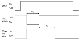
T1 : 0.7s(Min), T2 : 0.7s±0.1s
Under IGN2 switch ON & Wiper Int switch ON states, and wiper int volume value are acquired and intermittent time is calculated. then, wiper intermittent time is automatically converted.
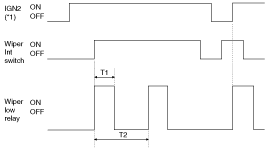
T1 : 0.7 ± 0.1s, T2 : INT Time( 2.2 ± 0.2s ~ 10 ± 1s)
*1 ON : IGN2 = ON OFF: IGN2 = OFF
Wiper Control Precaution
Variable int wiper
Wiper low relay time is 0.7s ±0.1s.
Intermittent time is from output ON to the next output ON.
Wiper low relay output is continued for remaining ON time if INT switch is turned OFF during output.
Intermittent time is restarted when IGN2 switch is ON and wiper Int switch is changed from OFF to ON.
Intermittent time is restarted when wiper int switch is ON and IGN2 switch is changed from OFF to ON
2.5V is used when volume value is 2.5V or more.
Input voltage (Volume) | Intermittent time (sec) ±10% | Remarks |
Speed is fixed | ||
0.0V | 2.2 Sec |
|
1.0V | 3 Sec |
|
1.5V | 3.8 Sec |
|
2.0V | 5.6 Sec |
|
2.5V | 10 Sec |
|
Buzzer sound spec
Priority | Name | Cycle | Duration |
1 | RPAS warning | - | - |
2 | Seatbelt warning | 1s / Reductive | Spec |
3 | Overspeed warning | - | - |
4 | Key operated warning | 1s / Reductive | Infinite |
5 | Key learning sound (NON SMK option) | 0.6s/Reductive | 3s |
6 | Parking brake warning | 0.6s / Reductive | Infinite |
Buzzer output
Buzzer output to estimate BCM int buzzer in cluster, and data transmission.
※ Internal buzzer is used for rear parking assist system.
State | Description |
Initial Condition | IGN1 OFF |
Event | C_DRV Seat Belt SW is belted and IGN1=ON |
Action | - Start 5.7 seconds driver indicator blinking - The automaton state is changed to IGN1 ON DRIVER BELTED |
State | Description |
Initial Condition | IGN1 OFF |
Event | C_DRV Seat Belt SW is unbelted and IGN1=ON |
Action | - Start 6 seconds blinking for C_DRVSeatbeltIND - Start 5.7 seconds warning for C_IntBuzzer - The automaton state is changed to IGN1 ON DRIVER UNBELTED |
State | Description |
Initial Condition | IGN1 ON DRIVER BELTED |
Event | IGN1=OFF |
Action | - Stop 6 seconds blinking for C_DRVSeatbeltIND - Stop 5.7 seconds warning for C_IntBuzzer - The automaton state is changed to IGN1 OFF |
State | Description |
Initial Condition | IGN1 ON DRIVER BELTED |
Event | C_DRV Seat Belt SW is unbelted |
Action | - Start 6 seconds blinking for C_DRVSeatbeltIND - Start 5.7 seconds warning for C_IntBuzzer - The automaton state is changed to IGN1 ON DRIVER UNBELTED |
State | Description |
Initial Condition | IGN1 ON DRIVER UNBELTED |
Event | IGN1=OFF |
Action | - Stop 6 seconds blinking for C_DRVSeatbeltIND - Stop 5.7 seconds warning for C_IntBuzzer - The automaton state is changed to IGN1 OFF |
State | Description |
Initial Condition | IGN1 ON DRIVER UNBELTED |
Event | C_DRV Seat Belt SW is belted |
Action | - Stop 5.7 seconds warning for C_IntBuzzer - The automaton state is changed to IGN1 ON DRIVER BELTED |
From IGN1 switch ON, Warning lamp for 1sec (DUTY 50%) and Chime buzzer for 6 time every 1sec. (in case of S/BELT unfastened state) But, within 6sec in the S/BELT fastened, the Chime buzzer output is stop, and Warning lamp is the remaining time.
Lamp and Chime buzzer become output stop when IGN1 is turned OFF within 6sec-output.
If vehicle speed over 10Km/h, Warning lamp and Chime buzzer will operate when Seat belt unfastened after IGN ON.
If vehicle speed below 5Km/h or IGN OFF or seat belt fastened, the pattern is stopped.
Seat belt fastened→unfastened when IGN1=ON state : if vehicle speed over 10Km/h,1time output. And if vehicle speed 5~10Km/h, Warning lamp for 1sec (DUTY 50%) and Chime buzzer for 6 every 1s. If vehicle speed less than 5Km/h, Warning lamp for 6 every 1sec (DUTY 50%)
Internal buzzer on every 1sec when driver door switch is on and key ign on.
Output is off if key ign is in off and driver door switch closed are met during Internal buzzer output.
At IGN1 on, output is off.
T1 : 1 ± 0.1sec
KEY IN ON : Key in switch ON or ACC ON or fob in ON
KEY IN OFF : Key in switch OFF and ACC OFF and fob in OFF
Function | Characteristics | Name | |
Hardware Label | Spec. Designation | ||
Input | Logic | C_ParkingBrakeSW | Parking Brake Switch |
L_IGN1 | Ignition 1 Input | ||
CAN Communication | C_VehicleSpeed | Vehicle Speed from CLU | |
Output | CAN Communication | C_IntBuzzer | Internal Warning Buzzer |
0 : OFF / | |||
1 : SeatBelt Warning / | |||
2 : Key Operated Warning/ | |||
3 : Parking Brake Warning / | |||
4 : Reserved | |||
5 : Key Learning Sound(No SMK Option) | |||
6 : default | |||
Behavior Characteristics
If driver drives the vehicle with non-parking brake or not completely released and vehicle speed exceeds the specific value of 5km/h, a sound warning reminds the driver that parking brake has to be released.
Parameter Values
Type | Magnetic Buzzer |
Parking Brake Warning Buzzer Sound frequency | 800 Hz |
Parking Brake Warning Buzzer Sound Signal Duty Ratio | 50% Duty |
Parking Brake Warning Buzzer Sound Period | 0.6 + 0.06 sec |
Parking Brake Warning Buzzer Sound duration | Infinite |
O_KeyHoleIllumination is turned ON at L_IGN1 = OFF & C_DRVDRSW(OR C_ASTDRSW) = OPEN.
After 20min at (1) State, O_KeyHoleIllumination output is turned OFF.
At (1) State, if C_DRVDRSW(OR C_ASTDRSW ) is closed O_KeyHoleIllumination output continue ON state during 30s and after turned OFF.
At (1) State, when L_IGN1 is turned ON O_KeyHoleIllumination is immediately turned OFF.
If ATWS state are ON, O_KeyHoleIllumination is immediately turned OFF.
T1 : 30 ± 1sec
Defogger relay & Front deicer relay is turned ON for 20min if defogger switch ON after Alt L ON & IGN1 ON.
Defogger relay & Front deicer relay is turned OFF if again defogger switch ON during defogger relay ON.
Defogger relay & Front deicer relay is turned OFF if AltL OFF or IGN1 OFF during defogger relay ON.
Defogger relay & Front deicer relay and OFF of the output will remain at Defogger switch ON & Alt LON.
T1 : 20 ± 1min
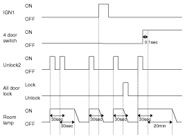
IGN1 off the door (Trunk excluded) will be lit to open the room lamp.
Room lamp 4 Door closes, a 30-second delay will be lights out.
4 Door in closed IGN1 off & (Key in → Key out): 30-second delay will be lights out.
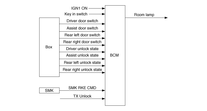
※ TX UNLOCK : Include UNLOCK by KEYLESS or SMK
※ IGN KEY=IN->OUT
: IGN KEY=ON->OFF & ACC=ON->OFF & IGN1=ON->OFF & IGN2=ON->OFF
※ b_4DOORSW
: b_4DOORSW = ON (C_DRVDRSW=OPEN or C_ASTDRSW=OPEN or C_RLDRSW=OPEN or C_RRDRSW=OPEN)
: b_4DOORSW = OFF (C_DRVDRSW=CLOSE & C_ASTDRSW=CLOSE & C_RLDRSW=CLOSE & C_RRDRSW=CLOSE)
Room Lamp off
State | Description |
Initial Condition | Room lamp decaying |
Event | Decay finished |
Action | Room lamp off |
Room Lamp on
State | Description |
Initial Condition | Room Lamp off |
Event | IGN1 on & 4door switch on |
Action | Room Lamp on |
State | Description |
Initial Condition | Room Lamp Decaying |
Event | IGN1 on & b_4DRSW=on |
Action | Room Lamp on |
State | Description |
Initial Condition | Room Lamp on for 20min |
Event | IGN1 on |
Action | Room Lamp on |
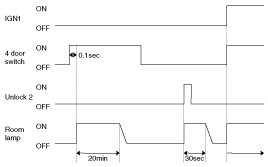
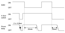
Room Lamp on for 30s
State | Description |
Initial Condition | Room Lamp on for 30s |
Event | TX Unlock or Key In switch on→off |
Action | Restart Room Lamp on for 30s |
State | Description |
Initial Condition | Room Lamp on |
Event | IGN1 off & b_4DRSW=off |
Action | Start Room Lamp on for 30s |
The flickering of lamp is not allowed even though IGN1 ON
The resolution of Decayed Room Lamp must be more than 32 step.
State | Description |
Initial Condition | Room Lamp on for 20min |
Event | IGN1 off & b_4DRSW=off |
Action | Start Room Lamp on for 30s |
State | Description |
Initial Condition | Room Lamp Decaying |
Event | IGN1 off & b_4DRSW=off & (TX Unlock or Key In switch on→off) |
Action | Start Room Lamp on for 30s |
State | Description |
Initial Condition | Room Lamp off |
Event | IGN1 off & b_4DRSW=off & (TX Unlock or Key In switch on→off) |
Action | Start Room Lamp on for 30s |
Room Lamp Decaying
State | Description |
Initial Condition | Room Lamp on for 30s |
Event | IGN1 on or 30s elapsed or Any Door Unlock→All Door Lock1 |
Action | Start Room Lamp Decaying |
State | Description |
Initial Condition | Room Lamp on |
Event | IGN1 on or b_4DRSW=off |
Action | Start Room Lamp Decaying |
State | Description |
Initial Condition | Room Lamp on for 20min |
Event | 20min elapsed or (IGN1 off & b_4DRSW=off & All Door Lock1) |
Action | Start Room Lamp Decaying |
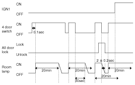
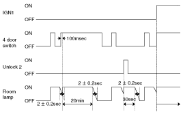
Room Lamp on for 20min
State | Description |
Initial Condition | Room Lamp off |
Event | IGN1 off & (b_4DRSW=off→on for 100ms) |
Action | Start Room Lamp on for 20min |
State | Description |
Initial Condition | Room Lamp Decaying |
Event | IGN1 off & (b_4DRSW=off→on for 100ms) |
Action | Start Room Lamp on for 20min |
State | Description |
Initial Condition | Room Lamp on for 30s |
Event | IGN1 off & (b_4DRSW=off→on for 100ms) |
Action | Start Room Lamp on for 20min |
State | Description |
Initial Condition | Room Lamp on |
Event | IGN1 off & b_4DRSW=on |
Action | Start Room Lamp on for 20min |
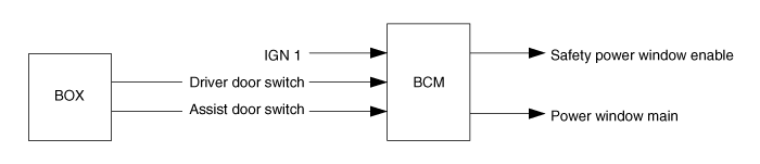
Safety Power window Enable and power window main output is turned ON at IGN1 ON.
Maintaining output at IGN1 OFF after 30 seconds Safety Power window Enable and power window main, Safety Power window Enable and power window main output is OFF.
Above (2) Driver door switch or Assist door switch in protest to the conditions when you OPEN, Safety Power window Enable and power window main output will be OFF immediately.
IGN1 OFF when the Safety Power window Enable and power window main output is OFF at driver door switch or Assist door switch OPEN.
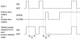
T1 : 30 ± 3sec
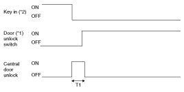
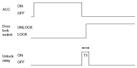
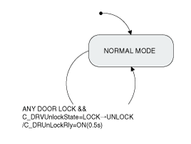
ALL DOOR LOCK output is ON during T1(0.5s) if C_DRVUnlockState or C_ASTUnlockState is LOCK within 3sec after C_DRVKeyLockSW is turned ON. But, KEY IN ON & L_IGN1 ON when output is prohibited.
C_DoorUnlockRly output is ON during T1(0.5s) if C_DRVUnlockState is UNLOCK within 3sec after C_DRVKeyUnlockSW is turned ON.
C_DoorUnlockRly output is ON during T1(0.5s) if C_ASTUnlockState is UNLOCK within 3sec after C_ASTKeyUnlockSW=ON is turned ON.
ALL DOOR LOCK output is ON during T1 at TXLock ON or C_ C_SMKRKECMD = LOCK or C_PassiveLock ON.
ALL DOOR UNLOCK output is ON during T1 at TXUnlock ON or C_ SMKRKECMD = UNLOCK or C_PassiveUnlock ON(NA C_P_FR=ON).
ALL DOOR LOCK output is ON during T1 at C_PwdwDRLockSW=ON.
ALL DOOR UNLOCK output is ON during T1 at C_PwdwDRUnlockSW=ON. But, C_PwdwDRUnlockSW=ON signal is ignored in ARM, ARMWAIT,REARM, ALARM state.
LOCK/UNLOCK by (8) C_DRVUnlockState, C_ASTUnlockState operation is not interlocked. (mechanical operation)
Shall be no malfunction at Battery connection. (shall be no malfunction even at L_KeyInSW).
When the output of the reverse direction is required and the current output immediately OFF, after 100ms delay and output to the reverse. But, during 100ms delay when output is required the output needs to eventually send us the output.
If LOCK output and UNLOCK output conditions at the same time, LOCK output is done, and the UNLOCK output is ignored.
If ALL DOOR LOCK state of the output conditions at ALL DOOR LOCK status, the actual output is not,and ALL DOOR UNLOCK state of the output conditions at ALL DOOR UNLOCK status, the actual output is not.
ALL DOOR LOCK(UNLOCK) SW always output LOCK(UNLOCK) requirement by C_PwdwDRLockSW(C_PwdwUnlockSW), TXLock, TXUnlock, C_SMKRKECMD=LOCK,C_SMKRKECMD=UNLOCK, C_DRVKeyLockSW, C_DRVKeyUnlockSW, C_ASTKeyUnlockSW regardless of LOCK(UNLOCK) state.
At IGN1 ON, LOCK output is prohibited by DOOR KEY LOCK SW.
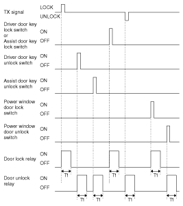
T1 : 0.5 ± 0.1sec
ALL DOOR UNLOCK output is ON during T3 if C_DRVUnlockSW is UNLOCK within 3s andC_DRVKeyUnlockSW is OFF->ON within T1 after C_DRVKeyUnlockSW is OFF -> ON (mechanically, C_DRVUnlockSW is unlocked and BCM signal doesn’t output).
ALL DOOR UNLOCK output is ON during T3 if C_DRVUnlockSW is UNLOCK within 3s and TXUnlock is received within T1 after C_DRVKeyUnlockSW is OFF -> ON (mechanically, C_DRVUnlockSW is unlocked and BCM signal doesn’t output).
DRIVER DOOR UNLOCK output is ON during T3 when TXUlock signal is received. But, ALL DOOR UNLOCK output are ON during T3 if TX Unlock signal is received within T1.
ALL DOOR UNLOCK output is ON during T3 if C_DRVKeyUnlockSW is OFF->ON (mechanically,C_DRVUnlockSW is unlocked and BCM signal doesn’t output) within T1 after TXUnlock received and C_DRVUnlockSW is UNLOCK within 3s.
When other registered TXUnlock signal is received within T1, they are regarded as the same TX.
At C_DRVUnlockSW UNLOCK state, the DRIVER DOOR UNLOCK requirement does not output.
DRIVER DOOR UNLOCK output will be according to ALL DOOR UNLOCK output when the DRIVER DOORUNLOCK output of the ALL DOOR UNLOCK output requirements.
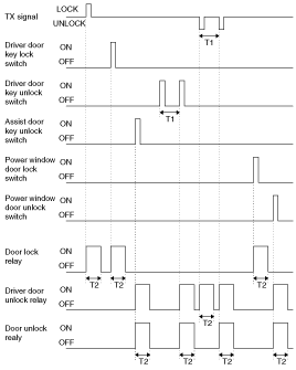
T1 : 4 ± 1sec, T2 : 0.5 ± 0.1sec
ALL DOOR UNLOCK output is ON during T3 if C_DRVUnlockSW is UNLOCK within 3s and C_DRVKeyUnlockSW is OFF->ON within T1 after C_DRVKeyUnlockSW is OFF -> ON (mechanically, C_DRVUnlockSW is unlocked and BCM signal doesn’t output).
ALL DOOR UNLOCK output is ON during T3 if C_DRVUnlockSW is UNLOCK within 3s and C_SMKRKECMD = UNLOCK is received within T1 after C_DRVKeyUnlockSW is OFF -> ON (mechanically, C_DRVUnlockSW is unlocked and BCM signal doesn’t output).
DRIVER DOOR UNLOCK output is ON during T3 when C_SMKRKECMD = UNLOCK signal is received. But, ALL DOOR UNLOCK output are ON during T3 if C_SMKRKECMD = UNLOCK signal is received within T1.
ALL DOOR UNLOCK output is ON during T3 if C_DRVKeyUnlockSW is OFF->ON (mechanically,C_DRVUnlockSW is unlocked and BCM signal doesn’t output) within T1 after C_SMKRKECMD = UNLOCK received and C_DRVUnlockSW is UNLOCK within 3s.
DRIVER DOOR UNLOCK output is ON during T3 when C_PassiveUnlock ON & C_P_FL ON is input. But, ALL DOOR UNLOCK output is ON during T3 if C_PassiveUnlock ON & C_P_FL ON is input within T1.
DRIVER DOOR UNLOCK output is ON during T3 when C_PassiveUnlock ON & C_P_FL ON is input. But, ALL DOOR UNLOCK output is ON during T3 if C_DRVKeyUnlockSW is OFF -> ON & C_P_FL ON is input within T1.
DRIVER DOOR UNLOCK output is ON during T3 when C_PassiveUnlock ON & C_P_FL ON is input. But, ALL DOOR UNLOCK output are ON during T3 if C_SMKRKECMD = UNLOCK is received within T1.
At C_DRVUnlockSW UNLOCK state, the DRIVER DOOR UNLOCK requirement does not output.
DRIVER DOOR UNLOCK output will be according to ALL DOOR UNLOCK output when the DRIVER DOORUNLOCK output of the ALL DOOR UNLOCK output requirements.
This function is not performed when vehicle speed is more than 3km/h.
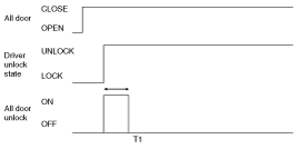
ALL DOOR UNLOCK signal is output for 1s after 0.5s from when the state becomes IGN KEY ON& C_DRVDRSW = OPEN & C_DRVUnlockState = LOCK.(Except NA)
DRIVER DOOR UNLOCK signal is output for 1s after 0.5s from when the state becomes IGN KEY ON& C_DRVDRSW = OPEN & C_DRVUnlockState = LOCK.(Only NA)
ALL DOOR UNLOCK signal is output for 1s after 0.5s from when the state becomes IGN KEY ON & C_ASTDRSW = OPEN & C_ASTUnlockState = LOCK.
ALL DOOR UNLOCK signal is output for 1s after 0.5 from when (1),(2),(3) concurrent satisfaction, (3) paragraph pursuant (Except DEAD LOCK)
UNLOCK signal is output 3 times as Max (1s-output is excluded) in case LOCK state is held even when UNLOCK signal is output for 1s in (2),(3),(4). (1s cycle: 0.5s ON/OFF)
After (6) of Section, when C_DRVDRSW is CLOSE CENTRAL UNLOCK in the LOCK state attempts one-time attempt.
ALL DOOR UNLOCK signal is output (only once) during 1s if C_DRVDRSW is CLOSE within 0.5s from C_DRVUnlockState UNLOCK -> LOCK under IGN KEY ON.(Except NA)
DRIVER DOOR UNLOCK signal is output (only once) during 1s if C_DRVDRSW is CLOSE within 0.5s from C_DRVUnlockState UNLOCK -> LOCK under IGN KEY ON.(Only NA)
ALL DOOR UNLOCK signal is output (only once) during 1s if C_ASTDRSW is CLOSE within 0.5s from C_ASTUnlockState UNLOCK -> LOCK under IGN KEY ON.
ALL DOOR UNLOCK signal is output (only once) during 1s if C_DRVUnlockState is UNLOCK->LOCK within 0.5s from C_DRVDRSW OPEN -> CLOSE under IGN KEY ON.(Except NA)
DRIVER DOOR UNLOCK signal is output during 1s if C_DRVUnlockState is UNLOCK->LOCK within 0.5s from C_DRVDRSW OPEN -> CLOSE under IGN KEY ON.(Only NA)
ALL DOOR UNLOCK signal is output (only once) during 1s if C_ASTUnlockState is UNLOCK->LOCK within 0.5s from C_ASTDRSW OPEN -> CLOSE under IGN KEY ON.
At IGN KEY=ON after C_DRVDRSW or C_ASTDRSW is OPEN if the C_PwdwDRLockSW ON, KEY REMINDER function is performed.
Judgment of the possibility of RETRY signal output is performed at RETRY signal output start.
(after 1.5s from the first UNLOCK signal output)
After the condition if UNLOCK is met, UNLOCK signal is output if the condition is not held for 0.5s. But, UNLOCK signal is not output if KEY IN is OFF at the moment that 0.5s passes after the condition is met by C_DRVUnlockState or C_ASTUnlockState change from UNLOCK to LOCK.
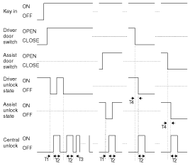
T1,T3 : 0.5 ± 0.1sec, T2 : 1 ± 0.1sec, T4 : 0.5sec Max
KEY IN ON : Key in ON or ACC = 1 or IGN1 ON or IGN2 ON
KEY IN OFF : Key in OFF and ACC =0 and IGN1 OFF and IGN2 OFF
IGN KEY ON : Key in switch(Fob in) ON or ACC ON or IGN1 ON or IGN2 ON
IGN KEY OFF : Key in switch(Fob in) OFF and ACC OFF and IGN1 OFF and IGN2 OFF
This function is not performed when vehicle speed is 3km/h or more.
When the driver door switch (Assist door switch) = OPEN and driver unlock state (Assist unlock state) are lock state, passive KEY REMINDER signal received at the output ALL DOOR UNLOCK is for 1s.
UNLOCK signal is output 3 times as Max (1s-output is excluded) in case LOCK state is held even when UNLOCK signal is output for 1s in (2). (1s cycle: 0.5s ON/OFF)
T1 : 1 ± 0.1sec, T2 : 0.5 ± 1sec
When IGN1 = ON, L_CRASH INPUT signal starts to judge ON/OFF from T1(1s), When IGN_KEY_OFF, L_CRASH INPUT signal terminates to judge ON/OFF.
After L_CRASH INPUT signal starts to judge ON/OFF and IGN_KEY_ON states , if L_CRASH INPUT is ON then ALL DOOR UNLOCK is output for T2(5s) (CRASH UNLOCK OUTPUT)
* L_CRASH INPUT signal is determined L_CRASH INPUT = ON, when 16ms_LOW / 4ms_HIGH cycle is input 1 time.
* In BCM SLEEP state, L_CRASH INPUT is ignored.
After above (2) Section. even if IGN KEY is ON ⇒ OFF during the CRASH UNLOCK output, CRASH UNLOCK is maintained for the remaining time.
After above (2) Section. If L_CRASH INPUT is ignored to input again during CRASH UNLOCK output for T2.
CRASH UNLOCK output before BCM SLEEP states to the ANY DOOR UNLOCK⇒LOCK then ALL DOOR UNLOCK output is performed during T2.
CRASH DOOR UNLOCK condition, AUTO DOOR LOCK does not function.
CRASH DOOR UNLOCK function overrides LOCK / UNLOCK control by other functions.
DOOR UNLOCK is outputting and after output, LOCK / UNLOCK request by other function is ignored.
After CRASH DOOR UNLOCK, to enter BCM SLEEP states or L_KEY IN = OFF & L_ACC = OFF &L_IGN1 = OFF & L_IGN2 = OFF are became then LOCK / UNLOCK control by the other function is performed.
T1 : 5.0 sec
* IGN KEY_ON : ON == KEY IN or ACC ON or IGN1 ON or IGN2 ON
OFF == KEY OUT & ACC OFF & IGN1 OFF & IGN2 OFF
L_CrashInput for the input signal ON / OFF judging criteria are the following figure.
T1 : 1 ± 0.1sec, T2 : 0.5± 0.1sec
ALL DOOR LOCK signal is output if vehicle speed is 15km/h within T1 under IGN1 ON && Alt L ON. But ALL DOOR LOCK , All DOOR LOCK signal is not output if all DOOR is LOCK or ALL DOOR are FAIL.
LOCK signal is output 3 times as Max if either one DOOR is UNLOCK after LOCK signal output in (2).(1s cycle) But, DOOR, which is LOCK from UNLOCK state during 3-time output, is ignored.
Relevant DOOR is FAIL if the state is UNLOCK after 3-time output.
LOCK signal is output once if the FAIL DOOR is UNLOCK again after the DOOR is LOCK.
LOCK signal is output once if locked doors, which are LOCK state after LOCK signal output in (2), are unlocked again. But, LOCK signal is output once for the relevant DOOR even when UNLOCK state continues after LOCK signal output.
FAIL DOOR is cleared at IGN switch OFF.
AUTO DOOR LOCK function is not performed when CRASH UNLOCK condition is met.
AUTO DOOR LOCK function is not performed when set up L_SIDE AIR OPT = ON.
T1 : max 1.5sec, T2 : 0.5 ± 0.1sec
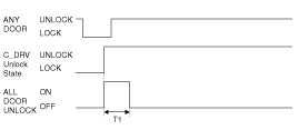
ANY DOOR UNLOCK ON driver Unlock State Unlock or assist Unlock State Unlock or rear left Unlock State or rear right unlock state
ANY DOOR UNLOCK OFF driver Unlock State Lock assist Unlock State Lock and rear left Unlock State and rear right unlock state
IGN1 ON & Alt L ON state of 100msec in the close future, and ANY DOOR UNLOCK ANY DOOR UNLOCK ALL DOOR (Driver door SW & Assist door SW & Rear left door SW & Rear right SW) in the conditions when Inhibit P, ON->OFF, ALL DOOR LOCK to the output.
AUTO DOOR LOCK function is not performed when CRASH UNLOCK condition is met.
ALL DOOR UNLOCK signal is output at IGN KEY IN→OUT. But, UNLOCK state that is ALL DOOR to UNLOCK does not output.
T1 : 0.5 ± 0.1sec
*1 ON(UNLOCK) : Driver Unlock State or assist Unlock State or rear left Unlock state or rear right unlock state = UNLOCK
OFF (LOCK) : Driver Unlock State & assist Unlock State & rear left Unlock state & rear right unlock state = LOCK
*2 KEY IN ON : Key in switch ON or ACC =1 or IGN1 ON or IGN2 ON
KEY IN OFF : Key in switch OFF and ACC =0 and IGN1 OFF and IGN2 OFF
Under under ANY DOOR LOCK, ALL DOOR UNLOCK signal is output at ACC ON→OFF.
T1:0.5s ± 0.1s
In Lock states of ANY DOOR (C_DRVUnlockState || C_ASTUnlockState || C_RLUnlockState || C_RRUnlockState), if C_DRVUnlockState is LOCK ⇒ UNLOCK, ALL DOOR UNLOCK is output one time for T1 .
T1:0.5s ±0.1s
ALL DOOR CLOSE & ANY DOOR LOCK state is the state of IGN1 & Alt L ON to OFF->ON when in Inhibit P after 300msec, CENTRAL DOOR UNLOCK is the output.
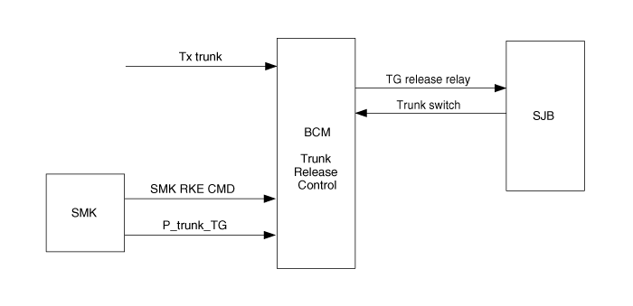
If TXTrunk is received, C_TGReleaseRly is ON for T1. (Non-SMK)
If C_SMKRKECMD Trunk signal is received, C_TGReleaseRly is ON for T1. (SMK)
Trunk control by TGReleaseRly SW is mechanical operation.
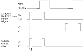
T1 : 500 ± 100msec
In L_IGN1 ON, C_InhibitP ON or C_InhibitN ON condition, if L_BrakeSW input is ON, O_ATMSOL output is ON to makes moving condition of SHIFT LEVER.
In L_IGN1 ON, vehicle speed is less than 7KPH and C_InhibitD ON conditions, if L_BrakeSW input is ON, O_ATMSOL output is ON to makes moving condition of SHIFT LEVER.
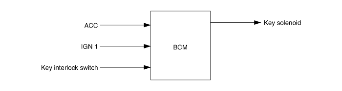
Key solenoid to the output of the ON KEY to make the subject does not fall. (If IGN1 ON or ACC subject to the key Interlock switch input is OFF.)
In addition to the above conditions, the KEY OFF key solenoid output to fall out, to make conditions.
Key solenoid output OFF -> ON operation, 0.9sec ~ 1.5sec for the 7 - 10V and the behavior, then the voltage 6 - 9V to maintain.
T1 : 0.9 ~ 1.5sec
Function | Characteristics | Name | |
Hardware Label | Spec. Designation | ||
Input | Logic | L_IGN1 | IGN1 |
L_KeyIn | Key In Signal | ||
L_IGN2 | IGN2 | ||
L_ACC | ACC | ||
L_TailSW | Tail Lamp Switch | ||
L_AutolightSW | Autolight Switch | ||
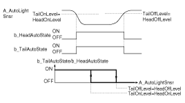
Internal | b_TailAutoState | Tail Lamp On/Off Request by Auto Light Control Module | |
b_Escort | Escort activation/deactivation Status | ||
CAN Communication | C_DRVDRSW | Driver Side Door Switch | |
Internal | b_KeyInMarker | Key Inserted state Marker | |
b_TailAutoCut | Auto Cut Status (Memorized in EEPROM) | ||
b_TailLampSWOn | On: | ||
L_TailSW = On || (b_TailAutoState = On &(b_IGN = On || b_START = On)) | |||
Off: | |||
L_TailSW = Off & (b_TailAutoState = Off || (b_TailAutoState = On & b_IGN = Off & b_START =Off)) | |||
b_DDSWMarker | Driver door opened during escort state marker | ||
Output | Internal | TailOn | On : C_EXTTailON==On && C_INTTailON==On |
Off : C_EXTTailON==Off && C_INTTailON==Off | |||
CAN Communication | C_EXTTailON | Tail Lamp On/Off command | |
C_INTTailON | Interior Tail Lamp On/Off command | ||
General Function Condition
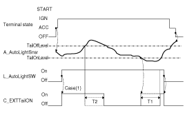
In BATTERY ON and Tail Lamp is off state, if user turns on the Tail Lamp switch (Tail switch ON), Tail Lamps are turned on.
Tail Auto Cut Function Condition
The “Tail Auto Cut” strategy ensures that Tail lamps are turned off even if a driver forgets to turn them off. When the Tail lamp is turned on by Tail lamp switch, after key insertion , and if a user removes key and opens the driver side door(or vice versa), the Tail lamps are automatically turned off. While “Tail Auto Cut” function is active, if a user turns off the Tail lamp switch or inserts key, “Tail Auto Cut” function will be deactivated and Tail lamps can be turned on.
“Tail Auto Cut” state is memorized in ECU, so even if battery reset, this state is not erased.
During the activation of Escort function, no Tail Auto Cut mode is possible and it is only after escort function deactivation that Tail Auto Cut mode can be applied.
CAN signal Tail Activity Condition
When tail lamp output condition is met, Tail Lamp activity CAN data (EXT Tail_Act & INT Tail Act) is also turned on. When tail lamp output condition is not met, Tail Lamp activity CAN data (EXT Tail Act & INT Tail Act) is also turned off.
Internal signal Tail Activity Condition
When tail lamp output is on, internal signal Tail Lamp activity (Tail Lamp) is also turned on.When tail lamp output is off, internal signal Tail Lamp activity (Tail Lamp) is also turned off.
HEAD LAMP CONTROL
Overview Description
This function describes the following features
Turn on and off Head Lamp Low by Head Lamp Low Switch input.
Turn on and off Head Lamp Low by Escort Function.
Turn on and off Head Lamp Low by Auto Light Control Request.
Turn on and off Head Lamp High by Head Lamp High Switch input.
Turn on and off Head Lamp High and Low by Passing Switch Input.
Output control of Head Lamp Low.
Output control of Head Lamp High.
Output control of Head Lamp High Indicator.
Output control of Head Lamp control for CANADA DRL.
Head Lamp Function Block diagram
Function | Characteristics | Name | |
Hardware Label | Spec. Designation | ||
Input | Digital | L_HeadLampLowSW | Head Lamp Low Switch |
L_AutoLightSW | Auto Light Switch | ||
L_HeadLampHighSW | Head Lamp High Switch | ||
L_IGN1 | Ignition1 power | ||
L_EC_DRL_OPT | Dedicated DRL option Switch | ||
CAN Communication | C_ALT_L | Engine is running | |
C_SMKRKECMD | SMK RKE Command from Fob | ||
C_DRVDRSW | Driver Side Door Open/Close Status | ||
C_PARKING BRAKE SW | Parking Brake Switch Status | ||
C_CANADA_DRLSts | DRL Option Switch | ||
C_D_DRL_Act | Dedicated DRL ON/Off State | ||
C_HLampLOW_Act | Head Lamp Low On/Off State | ||
C_HLampHIGH_Act | Head Lamp High On/Off State | ||
Internal | b_HeadAutoState | Head Lamp Low On/Off request by Auto Light Control Module | |
Internal | b_KeyOff | L_KeyIn == Off && L_ACC == Off && L_IGN1 == Off && L_IGN2 == Off | |
b_C_IGNSW | Same value with C_IGNSW(refer ECU spec.) | ||
b_IGN | on : b_C_IGNSW == IGN ON off : b_C_IGNSW == KEY OFF || b_C_IGNSW == KEY IN || b_C_IGNSW ==ACC ON || b_C_IGNSW ==ST | ||
b_ACC | on : b_C_IGNSW == ACC ON off : b_C_IGNSW == KEY OFF || b_C_IGNSW == KEY IN || b_C_IGNSW ==IGN ON || b_C_IGNSW ==ST | ||
b_START | on : b_C_IGNSW == ST off : b_C_IGNSW == KEY OFF || b_C_IGNSW == KEY IN || b_C_IGNSW ==ACC || b_C_IGNSW ==IGN ON | ||
b_HeadLampHighSW | This signal reserved for separated Head Lamp High input from Passing input | ||
b_PassingSW | On:L_HeadLampHighSW==OnOff:L_HeadLampHighSW==Off | ||
b_HeadLampLowSWOn | On: L_HeadLampLowSW == On || (b_HeadAutoState == On && (b_IGN == On || b_START == On)) Off: L_HeadLampLowSW == Off && b_HeadAutoState == Off | ||
b_LOCK | P_RKECMD == Lock || C_SMKRKECMD == Lock || C_PassiveLock == Lock | ||
b_2LOCK | b_LOCK counter | ||
b_Unlock | b_RKEUnLock==On || C_SMKRKECMD == UnLock || C_PassiveUnlock== UnLock | ||
b_DRLOpt | DRL Option | ||
Output
| Digital | O_HeadLampLowCTRL | Head Lamp Low Output Status (Active Low) |
Internal | b_Escort | Escort activation/deactivation Status | |
b_HeadLampHighOutput | On: C_HeadLampHighON = OnOff: C_HeadLampHighON = Off | ||
b_HeadLampLow | Internal Head Lamp Low activity | ||
b_HeadLampHigh | Internal Head Lamp High activity | ||
b_DRLOut | DRL Option activation/deactivation Status | ||
CAN Communication | C_CANADA_DRLON | CANADA DRL ON Command | |
C_D_DRL_ON | DEDICATED DRL ON Command | ||
C_HeadLampLowON | Head Lamp Low On/Off command | ||
C_HeadLampHighON | Head Lamp High On/Off command | ||
C_EXTTailON | EXTTail On/Off command | ||
Head lamp low signal control
Head Lamp Low control output is ON if HEAD LAMP LOW output is ON by ‘Head Lamp Low switch ON ‘ or ‘AUTO LIGHT function’.
Head Lamp Low control output is OFF when HEAD LAMP LOW output is ON->OFF.
Head lamp high control
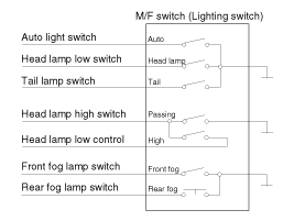
Head Lamp High input and Head Lamp Passing input by M/F is Head Lamp High switch processing for single input same MULTI-FUNCTION WIRING DESCRIPTION as Head Lamp High switch only input.
Head Lamp High Input
When Head Lamp High switch ON that in IGN2 ON and Head Lamp Low control output is ON by IMP, Head Lamp High is consider as input.
Head Lamp Passing Input
When Head Lamp High switch ON that in IGN2 ON and Head Lamp Low control output is OFF, Head Lamp Passing is consider as input.
Multi-function wiring description
Head Lamp Low Control
In IGN terminal State (IGN ON), if turn on the Head Lamp LOW switch(Head Lamp Low switch ON),
Head Lamp LOW outputs are turned on (Head Lamp Low ON).
When Tail lamp Off and headlamp Off conditions are satisfied at the same time, Head Lamp LOW and Tail LAMP turned off simultaneous immediately.
Head Lamp High Control
In IGN terminal State(IGN ON) and Head Lamp Low switch On(Head Lamp Low switch ON), if turn on the Head Lamp High switch(Head Lamp High switch ON), Head Lamp High Outputs are turned on (Head Lamp High ON).
Passing Control
In IGN terminal State(IGN ON), If Head Lamp Passing switch Input(Head Lamp High switch ON & Head Lamp Low control OFF) is detected then Head Lamp High Output(Head Lamp High ON) are turned on and Head Lamp Low Output(Head Lamp Low ON) at the same time.
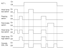
Canada DRL
If alternator level is high(ALT L=On), BCM activates Canada DRL functionality and turns on the Head lamp high (CANADA DRL=On).
Deactivation if:
Head lamp low On request by Head lamp switch or auto light head lamp Low control or
Head high On request by passing switch or
Parking brake switch On
Escort Function
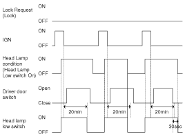
After user generates the call of head lamp low light(Head Lamp Low switch On), if switch off ignition(IGN Off and START Off), and then keep Head Lamp Low Output On (Head Lamp Low ON)state during 20min.
And after open and close driver side door(Driver door switch ON -> Driver door switch Off), user will have consequently lighting of head lamp low(Head Lamp Low ON) during only 30sec.
During active “Escort Function”, if receive Lock request 2 times (2 LOCK) or cancel the lighting request of head lamp low (Head Lamp Low switch Off & Auto Light switch Off), this function is released.
Lock request counting for 2 times (2 LOCK) is each follow cases:
RKE CMD == Lock
SMK RKE CMD == Lock
Passive Access Lock== Lock
If open the Driver door(Driver door switch ON) or close(Driver door switch Off), former lock counter is cleared, and start new 2 times lock counting.
Head Lamp Welcome Function
"Multifunction switch head lamp or auto light position and lock stated, if remote unlock, and then keep head lamp output on state during 15second.Lighting state, if remote lock and unlock, immediately light turn off."
While escort function is activated, Tail lamp is keeping the turn on state and does not go to Auto cut and after finish escort state and user removes key, it can go Auto cut mode.
While the “Escort Function” is activated by ‘Head Lamp Low Switch’, if change from ‘Head Lamp Low Switch’ to ‘Lamp Auto Switch’, “Escort Function” is deactivated, because Lamp Auto mode is ‘Lamp Off’ condition.
While the “Escort Function” is activated by ‘Lamp Auto Switch’, if change from ‘Lamp Auto Switch’ to ‘Head Lamp Low Switch’, “Escort Function” is keeping the activation state, because of ‘Head Lamp On’ condition.
After IGN terminal off 20 minute timers is started, but as soon as door is opened and closed then 30sec timer is engaged.
Overview Description
This function describes the following features.
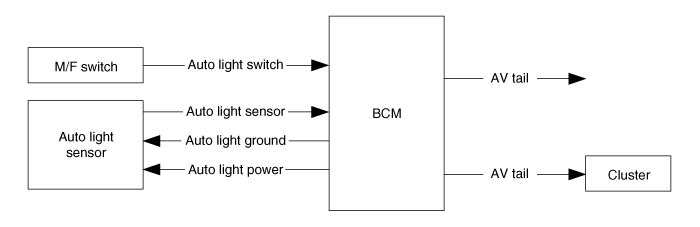
Input detection by Auto Light Sensor.
Generate Auto Light Out Status data.
Send Auto Light Out Status.
Tail Lamp Control by Auto light Mode.
Head Lamp Low Control by Auto light Mode.
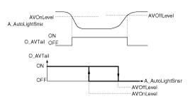
AV Tail Control by Auto Light sensor level.
Auto Light Mode State Diagram is based on Auto Light Sensor's level.
Power condition of Auto Light Action.
When CAN Wake-up, ACC, IGN, START terminal states, Auto Light Sensor operates.
Tail lamp | ON | 1.32 ± 0.1 V |
OFF | 3.24 ± 0.2 V | |
Head lamp | ON | 1.32 ± 0.1 V |
OFF | 3.24 ± 0.2 V | |
Filtering time | ON | 2.5 ± 0.1 Sec. |
OFF | 2.5 ± 0.1 Sec. |
Auto Light Control Function Block Diagram
Function | Characteristics | Name | |
Hardware Label | Spec. Designation | ||
Input | Logic | L_AutolightSW | Auto Light Switch |
Analog | A_AutoLightSnsr | Auto Light Sensor Level | |
Output | Internal | b_TailAutoState | Tail Lamp On/Off Request by Auto Light Control Module |
b_HeadAutoState | Head Lamp Low On/Off Request by Auto Light Control Module | ||
Logic | V_AutoLightGND | Supplying Ground to Auto Light Module | |
V_AutoLightPwr | Supplying Power to Auto Light Module | ||
O_AVTail | AV Tail output | ||
CAN Communication | C_AV_Tail | Auto Light output to AV module | |
During above ON/Off Filtering times, if a detected sensor value doesn’t satisfy the ON/Off condition, filtering time counter is cancelled. When Tail lamp Off and Headlamp Off conditions are satisfied at the same time, Head Lamp Low and Tail Lamp are turned off simultaneous.
These Filtering value is calibration value so it’s changeable.
In ACC terminal state, Tail Lamp and Head Lamp Low filtering times are not used; AV Tail Out filtering time is used even in ACC terminal state.
These filtering times shall have an error tolerance of +/-100msec
Continuous Turn ON Mode
CASE(1) : At the time that Tail Lamp and Head Lamp Low switch position are changed from manual ON to Auto ON position, if intensity of light measured by Auto light sensor that is already calculated satisfies the Head Lamp Low ON condition, Head Lamp Low is turned ON continuously without fluctuation
CASE(2) : In the hysteresis range between level On and level Off, the current state of Lamp is kept.
CASE(3) : As soon as the MFSW is changed to Off position, the lamp is turned Off immediately (Without Off delay times.)
Only in the terminal states of IGN and START, the Auto Light control functions of Tail lamp and head Lamp Low outputs can be active.
Overview Description
This function describes the following features
Turn on and off Front Fog Lamp by Front Fog Lamp switch input.
Versus variant (NA, Non-NA), function description
Front Fog Lamp Function Block Diagram
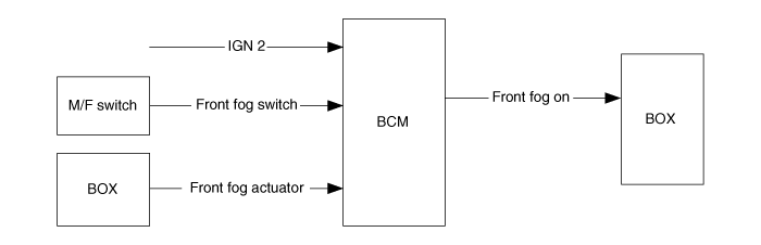
Function | Characteristics | Name | |
Hardware Label | Spec. Designation | ||
Input | Logic | L_IGN2 | ignition 2 |
L_FrontFogSW | Front Fog Switch Input | ||
Internal | b_TailLamp | Tail Lamp Output activation state | |
b_HeadLampLow | Head lamp low Output activation state | ||
b_HeadLampHigh | Head lamp high Output activation state | ||
Output | CAN Communication | C_FrontFogON | Front Fog Lamp Output |
Internal | b_FrontFogLamp | Front Fog Lamp Output activation state | |
Function Description
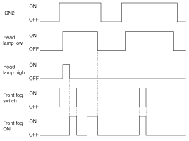
In case of (IGN2=ON) & (HeadLampLow=ON) & (HeadLampHigh=Off), if Front fog lamp switch input is detected (FrontFogSW=On), Front fog lamp output (FrontFogON=On) is turned ON.
If fails to activate front fog lamp output, indicator (FrontFogIND) is also turn off.