3.
Check motor operation by fuel pump connector (A) connecting power (No.4) and ground (No.5).
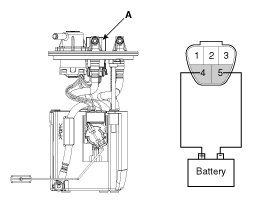
Pin No. | Description |
1 | Fuel sender signal |
2 | Fuel sender ground |
3 | Fuel sender (+) [+5V] |
4 | Fuel pump motor (+) [+12V] |
5 | Fuel pump motor (-) |
Turn the ignition switch OFF, and then remove battery (-) cable.
Remove the fuel pump assembly.
Check motor operation by fuel pump connector (A) connecting power (No.4) and ground (No.5).
Pin No. | Description |
1 | Fuel sender signal |
2 | Fuel sender ground |
3 | Fuel sender (+) [+5V] |
4 | Fuel pump motor (+) [+12V] |
5 | Fuel pump motor (-) |
Turn the ignition switch OFF, and then remove battery (-) cable.
Remove the fuel pump assembly.
Supply 4.5 voltage (1.5V battery 3EA) to the terminals 2 and 3.
Check voltage of the fuel sender normally.
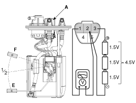
Pin No. | Description |
1 | Fuel sender signal |
2 | Fuel sender ground |
3 | Fuel sender (+) [+5V] |
4 | Fuel pump motor (+) [+12V] |
5 | Fuel pump motor (-) |
Also check that the resistance changes smoothly when the float is moved from "E" to "F".
Position | Output Voltage (Vref : 5V) | Capacity (ℓ) |
E | 0.2 ~ 0.4 | 2.7 |
1/2 | 2.34 ~ 2.64 | 28.3 |
Sender (F) | 4.4 ~ 4.6 | 54.6 |
Position | Output Voltage (Vref : 4.5V) | Capacity (ℓ) |
E | 0.17 ~ 0.37 | 2.7 |
1/2 | 2.18 ~ 2.38 | 28.3 |
Sender (F) | 3.95 ~ 4.15 | 54.6 |
