
The amount of intake air flow must be inputted to ECM in order to determine the fuel injection quantity. MAPS(Manifold Absolute Pressure) calculates the amount of air indirectly as measuring the pressure inside of intake manifold. This mechanism is called Speed-Density Type.
MAPS transfers analog output signal which is proportional to the change of intake manifold pressure, then, with this signal and RPM, ECM calculates the amount of intake air flow.
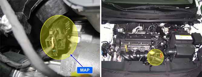
MAPS is mounted on surge tank to measure the pressure inside of intake manifold, and it consists of a piezo electric element and hybrid IC which amplifies output signal from the element. A piezo electric element is a sort of a diaphragm using piezo electric effect. One side of the diaphragm is surrounded with vacuum chamber while intake pressure is applied to the other side. Thus, signals are output by the transformation of diagphragm according to the change of pressure inside of intake manifold.
If sensor signal input is higher than 4.58V during 3 sec, ECM sets DTC P0108.
Item | Detecting Condition | Possible Cause |
DTC Strategy |
•
Signal check, high | 1. Poor connection 2. Open or short to power in signal circuit 3. Open in ground circuit 4. MAPS |
Enable Conditions |
•
Time duration for which signal voltage keeps over the threshold > 3 sec | |
Threshold Value |
•
Sensor voltage > 4.58V | |
Diagnostic Time |
•
Continuous | |
MIL ON Condition |
•
3 driving cycle |
Pressure [kPa] | 20 | 46.7 | 101.32 |
Voltage [V] | 0.79 | 1.84 | 4.0 |
As often as possible, the MAPS signal should be compared with the TPS signal. Check whether the MAPS and TPS signals increase at the same time when accelerating. During acceleration, the MAPS output voltage increases; during deceleration, the MAPS output voltage decreases.