

The APS is a very important sensor which controls the fuel amount by transmitting the driver's accelerating intention to ECM. And it is divided into APS 1,2 because its reliability is important. The APS 1,2 are composed with the independent power and ground. APS 2 shows the 1/2 output of the APS1 and decides the fault if the ratio of APS 1,2 is different. When the APS 1 is out of order, the signal of APS 2 can be substituted instead of APS 1 and vise versa.
Checking output signals from APS 2 under detecting condition, if output signals are below the threshold, ECM sets P2127.
Item | Detecting Condition | Possible Cause |
DTC Strategy |
•
Signal check, low | 1. Poor connection 2. Open or short to ground in power circuit 3. Open or short to ground in signal circuit 4. Faulty APS 5. Faulty ECM |
Enable Conditions |
•
Ignition "ON" | |
Threshold Value |
•
APS2 < 0.49V | |
Diagnostic Time |
•
0.14 sec | |
MIL ON Condition |
•
5 sec |
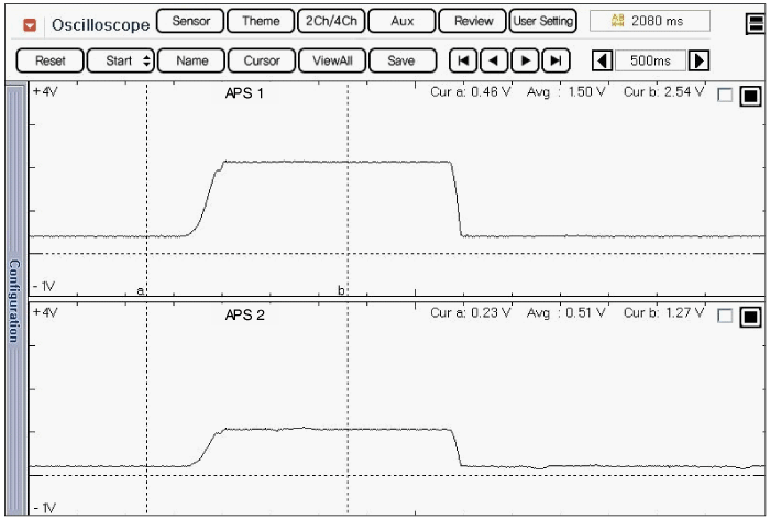
Fig.1) Normal waveform of APS1 & APS2 with acceleration
Signal waveform of APS 1 & 2 shows that APS 2 increases voltage just half of APS 1 voltage increase when accelerating.