Has a problem been found in any of the above areas?
 | ▶ Repair as necessary and go to "Verification of vehicle Repair" procedure. |
 | ▶ Go to "Compression pressure check" procedure. |
Remove cylinder’s spark plugs.
Visually/physically inspect the following items:
▶ Damaged insulation, Worn electrodes, Oil or fuel fouled, Loose terminals and cracks.
▶ Check for plug gap : 0.9 - 1.0 mm (0.035 - 0.039 in.)
▶ Check if the spark plug for the relevant cylinder is lighter in color than the other plugs.
Has a problem been found in any of the above areas?
 | ▶ Repair as necessary and go to "Verification of vehicle Repair" procedure. |
 | ▶ Go to "Compression pressure check" procedure. |
Warm up the engine to normal operating temperature.
Disconnect the spark plug cables. And remove the spark plugs and fuel pump relay.
Crank the engine to remove any foreign material in the cylinders.
Put compression pressure gauge into spark pulg hole.
Check compression pressure at each cylinder.
Specification : Approx. 15kg/㎠
Is compression pressure for each cylinder displayed within specifications ?
 | ▶ Go to "Ignition system check" procedure. |
 | ▶ Add a small amount of oil through the spark plug hole, and repeat above steps. If the addition of oil causes the compression to rise, the cause is a worn or damaged piston ring or cylinder inner surface. ▶ If the compression remains the same, the cause is a burnt or defective valve seat, or pressure is leaking from the gasket. Repair as necessary and go to "Verification of Vehicle Repair" procedure. |
IG KEY "OFF".
Disconnect Ignition coil connector.
Do visual inspection.
▶ Check contamination or damege on ignition coil.
IG KEY "ON" & ENG "OFF"
Measure the voltage between power terminal of ignition coil #1, #2, #3, #4 harness connector and chassis ground.
Specification : B+
Is the measured voltage within specifications ?
 | ▶ Go to "Ignition coil check" procedure. |
 | ▶ Repair Open or Short to ground in power circuit, and go to "Verification of Vehicle Repair" procedure. |
Measure the resistance between power and control terminal of ingnition coil connector #1, #2, #3, #4. (Component side / Primary coil)
Item | Specification |
Primary Coil Resistance (Ω) | 0.75Ω ± 15% [20 ℃ 68 ℉] |
Is the measured resistance within specifications ?
 | ▶ Go to "Timing mark check" procedure. |
 | ▶ Substitute with a known - good ignition coil and check for proper operation. If the problem is corrected, replace ignition coil and go to "Verification of Vehicle Repair" procedure. |
IG KEY "OFF".
Check the timing mark.
Is the timing mark normal?
 | ▶ Go to "Air leakage check" procedure. |
 | ▶ Repair and go to "Verification of Vehicle Repair" procedure. |
Visually/physically inspect the air leakage in intake/exhaust system as following items,
▶ Vacuum hoses for splits, kinks and improper connections.
▶ Throttle body gasket
▶ Gasket between intake manifold and cylinder head
▶ Seals between intake manifold and fuel injectors
▶ Exhaust system between HO2S and Three way catalyst for air leakage.
Has a problem been found in any of the above areas?
 | ▶ Repair or replace as necessary and go to "Verification of Vehicle Repair" procedure. |
 | ▶ Go to "PCV(Positive Crankcase Ventilation) valve check" procedure. |
IG KEY "OFF".
Disconnect PCV valve.
Check the movement of plunger by putting in and out a thin stick.
Is the movement of plunger normal?
 | ▶ Go to "Injector check" procedure. |
 | ▶ Substitute with a known - good PCV valve and check for proper operation. If the problem is corrected, replace PCV valve and go to "Verification of Vehicle Repair" procedure. |
IG KEY "OFF".
Remove injectors.
Check leakage or clog on injectors.
Measure the resistance between power and control terminal of the injector. (Component side)
Item | Specification |
Coil Resistance (Ω) | 13.8~15.2 [20°C 68°F] |
Is the measured resistance within specification ?
 | ▶ Go to "Fuel line check" procedure. |
 | ▶ Substitute with a known - good injector and check for proper operation. If the problem is corrected, replace injector and go to "Verification of Vehicle Repair" procedure. |
Check clog, contamination and damage on fuel line.
▶ Splits, kinks and improper connections of fuel line pipe.
▶ Interference, damage and improper connections of vacuum hose on fuel line.
▶ Improper connection of connectors on fuel line.
Is the fuel line normal?
 | ▶ Go to "Fuel pressure check" procedure. |
 | ▶ Repair as necessary and go to "Verification of Vehicle Repair" procedure. |
IG KEY "OFF".
Disconnect a fuel pump relay.
Engine start and wait until engine stop. and then key "OFF".
Install fuel pump relay.
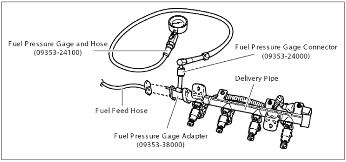
Connect fuel pressure guage using the correct adaptor.
Start the engine , and record fuel pressure.
Specification : Approx. 3.5㎏/㎠

Is the fuel pressure normal?
 | ▶ Many malfunctions in the electrical system are caused by poor harness(es) and terminals. Faults can also be caused by interference from other electrical systems, and mechanical or chemical damage. So, check poor connections and the related circuit between ECM and component thoroughly. Repair as necessary and go to "Verification of Vehicle Repair" procedure. |
 | ▶ Check clogging on the fuel filter. ▶ Check the fuel supply and return line. ▶ Repair as necessary and go to "Verification of vehicle Repair" procedure. |