
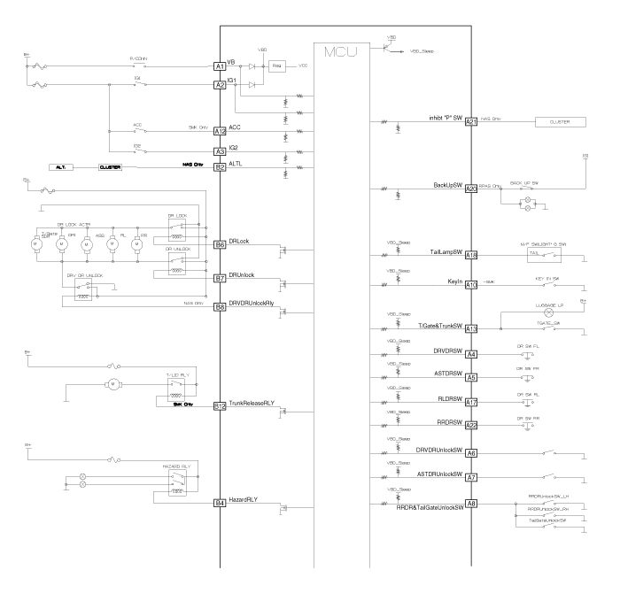
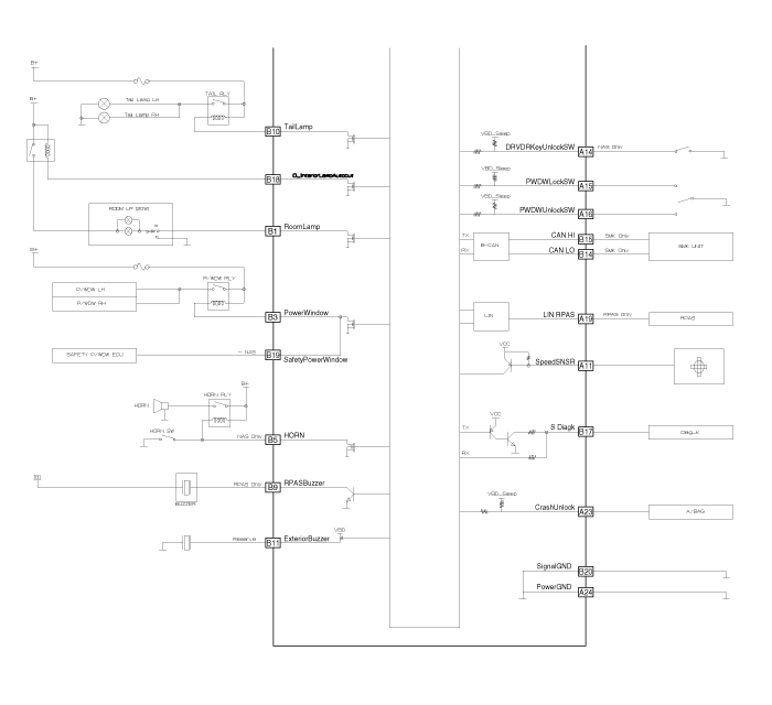
Pin | Connector A | Connector B |
1 | Battery | Room Lamp Output |
2 | Local ignition1 input in BCM | - |
3 | Local ignition2 input in BCM | Power Window Relay |
4 | Drive Door Switch | Hazard Relay |
5 | Assist Door Switch | - |
6 | Drive Door Unlock State input | Lock Relay |
7 | Assist Door Unlock State input | Unlock Relay |
8 | Rear Door(& Tail Gate) Unlock State input | - |
9 | - | RPAS Buzzer |
10 | Key in switch | Tail Lamp Relay |
11 | Speed Sensor | - |
12 | A_ACC | Trunk Release Relay(4DR), Tail Gate Unlock Relay(5DR) |
13 | Trunk Open Switch(4DR), Tail Gate Switch (5DR) | - |
14 | - | Body CAN Low |
15 | Power Window Lock Switch | Body CAN High |
16 | Power Window Unlock Switch | - |
17 | Rear Left Door Switch | KWP2000 terminal |
18 | Tail Lamp Switch | Interior lamp Autocut Output |
19 | LIN RPAS(Rear Parking Assist System) | Safety Power Window ECU Enable |
20 | Back Up Switch | Signal ground |
21 | - |
|
22 | Rear Right Door Switch | |
23 | Crash input from AIRBAG | |
24 | Power ground |
No. | Input Name | State | Voltage Level | INFO. | Chattering | Remark | |
Low | High | (msec) | |||||
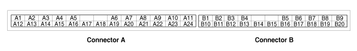
A1 | A_B+ | 9V~16V |
| - |
|
| BATTERY |
A2 | A_IGN1 | Off = GND On = BAT | 4V | 8V | Pull Down | 60 |
|
A3 | A_IGN2 | Off = GND On = BAT | 4V | 8V | Pull Down | 60 |
|
A4 | L_DRVDRSW | On = GND(OPEN) OFF=PullUp(CLOSE) | 2V | 6V | Pull Up VBD_SLEEP | 100 |
|
A5 | L_ASTDRSW | ↑ | ↑ | ↑ | ↑ | ↑ |
|
A17 | L_RLDRSW | ↑ | ↑ | ↑ | ↑ | ↑ |
|
A22 | L_RRDRSW | ↑ | ↑ | ↑ | ↑ | ↑ |
|
A13 | L_TrunkOpenSW or L_TailGateSW | ↑ | ↑ | ↑ | ↑ | ↑ |
|
A6 | L_DRVDRUnlockSW | On = GND(UNLOCK) Off = PullUp(LOCK) | ↑ | ↑ | ↑ | 60 |
|
A7 | L_ASTDRUnlockSW | ↑ | ↑ | ↑ | ↑ | ↑ |
|
A8 | L_RRDRUnlockSW Or L_RRDR&TailGateUnlockSW | On = GND (ANY DR UNLOCK) Off = Pull Up (ALL DR LOCK) | ↑ | ↑ | ↑ | ↑ |
|
A10 | L_KeyInSW | On = GND(KEY IN) Off=PullUp(KEY OUT) | ↑ | ↑ | ↑ | ↑ |
|
A12 | A_ACC | 9V~16V | 7.1V | 7.8V | Pull Down | 60 |
|
A11 | F_SpeedSNSR | Speed input=PULSE (0~5V) | 2V | 4V | OPEN COLLECTOR |
|
|
A17 | K_LINE | Diagnosis K-Line, Communication Line | - | - | - | - | - |
A23 | L_CrashInput | Normal: Duty 20% Crash: Duty 80% | - | - | PWM Period 20ms | - | - |
A15 | L_PwdwLockSW | On = GND(LOCK) Off=Pull Up(NORMAL) | 2V | 6V | PullUp VBD_SLEEP | 60 |
|
A16 | L_PwdwUnlockSW | On = GND(UNLOCK) Off = PullUp(NORMAL) | ↑ | ↑ | ↑ | ↑ |
|
A18 | L_TailLampSW | ON = GND OFF = Pull Up | ↑ | ↑ | ↑ | ↑ |
|
A19 | LIN_RPAS | LIN Communication Line | - | - | - | - |
|
A20 | L_BackUpSW | ON = BAT | 2V | 6V | Pull Down | 60 | A |
B15 | B_CAN_HI | Can Communication Line |
|
|
|
|
|
B14 | B_CAN_LO | Can Communication Line |
|
|
|
|
|