2.
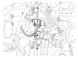
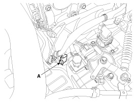
Dissconnect the solenoid valve connector (A) and inhibitor switch connector (B).
Remove the following items;
Engine cover.
Air duct and air cleaner assembly. (Refer to "Intake and Exhaust system" in EM group.)
Battery and battery tray. (Refer to "Charging system" in EE group.)
Dissconnect the solenoid valve connector (A) and inhibitor switch connector (B).
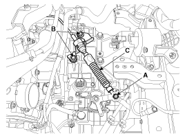
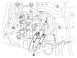
Remove the shaft cable (C) after removing the nut (A) and the bolts (B).
Tightening torque:
(A) 9.8 ~ 13.7 N.m (1.0 ~ 1.4 kgf.m, 7.2 ~ 10.1 lb-ft)
(B) 14.7 ~ 21.6 N.m(1.5 ~ 2.2 kgf.m, 10.9 ~ 15.9 lb-ft)
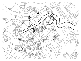
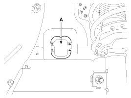
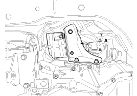
Remove the solenoid valve connector and inhibitor switch connector wiring mounting bracket (A).
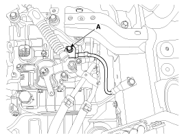
Remove the ground line after removing the bolt (A).
Remove the wiring mounting bolt (A).
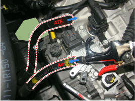
Disconnect the ATF cooler hose clamp(A).
Disconnect the ATF cooler hose(B) from the automatic transaxle cooler tube.
Carefully install the clamp not to damage the hose.
Install the clamp in a correct direction not to be interfered with other parts.
After the installation, start the engine and then check if there are any leakages from the hose.
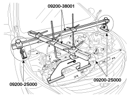
Using the engine support fixture (beam No.: 09200-38001 or 09200-3N000, supporter No.: 09200-2S000, adapter No.: 09200-4X000), hold the engine and transaxle assembly safely.
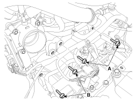
Remove the automatic transaxle upper mounting bolt (A-2ea) and the starter motor mounting bolt (B-2ea).
Tightening torque:
(A,B) 42.2 ~ 54.0 N.m (4.3 ~ 5.5 kgf.m, 31.1 ~ 39.8 lb-ft)
Remove the mounting cover (A).
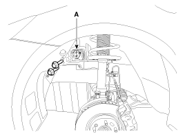
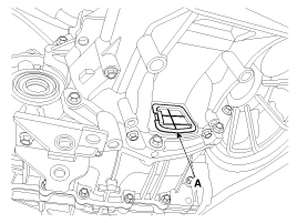
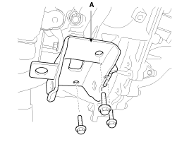
Remove the automatic transaxle mounting support bracket bolt (A).
Tightening torque:
88.3 ~ 107.9 N.m (9.0 ~ 11.0 kgf.m, 65.1 ~ 79.8 lb-ft)
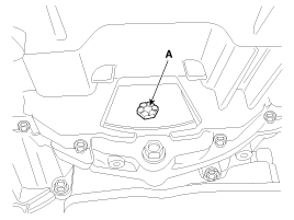
Remove the automatic transaxle support bracket (A).
Tightening torque:
58.8 ~ 78.5 N.m (6.0 ~ 8.0 kgf.m, 43.4 ~ 57.9 lb-ft)
Lift the vehicle with a jack.
Remove the under cover (A).
Tightening torque:
6.9 ~ 10.8 N.m (0.7 ~ 1.1 kgf.m, 5.1 ~ 8.0 lb-ft)
Remove the following items;
Drive shaft assembly. (Refer to "Drive shaft assembly " in DS group.)
Remove the heater protector (A).
Remove the air guide (A).
Remove the dust cover (A).
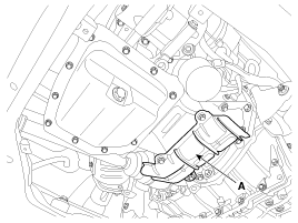
Remove the torque converter mounting bolts(A) with rotating the crankshaft pulley.
Tightening torque:
45.1 ~ 52.0 N.m (4.6 ~ 5.3 kgf.m, 33.3 ~ 38.3 lb-ft)
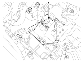
Remove the roll stopper (C) after removing the bolts (A) and (B).
Tightening torque:
(B) 49.0 ~ 63.7 N.m (5.0 ~ 6.5 kgf.m, 36.2 ~ 47.0 lb-ft)
(A) 107.9 ~ 127.5 N.m (11.0 ~ 13.0 kgf.m, 79.6 ~ 94.1 lb-ft)
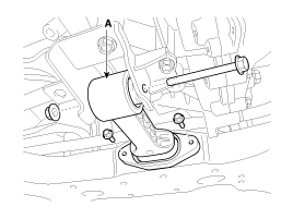
Remove the roll road support bracket (A).
Tightening torque :
49.0 ~ 68.6N.m (5.0 ~ 7.0kgf.m, 36.1 ~ 50.6lb-ft)
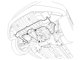
Remove the automatic transaxle with a jack after removing the mounting bolt (A-2ea, B-3ea).
Tightening torque:
(A) 42.2 ~ 53.9 N.m (4.3 ~ 5.5 kgf.m, 31.1 ~ 39.8 lb-ft)
(B) 42.2 ~ 48.1 N.m (4.3 ~ 4.9 kgf.m, 31.1 ~ 35.4 lb-ft)
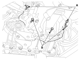
Be careful not to damage other system or parts near by when removing the transaxle assembly.
Installation is the reverse of removal.
Perform procedures below when replacement or reinstallation of the automatic transaxle assembly .
• In case of reinstalling the automatic transaxle.
If the differential oil seal is damaged and fluid is leaking, replace the oil seal with a new one. When installing the new oil seal, use the special tool.
Differential oil seal installer SST No.
A6GF1, A6MF1-1 → SST No.:09452-26100, 09231-H1100
A6MF1, A6MF2-1 → SST No.:09453-3L241, 09231-H1100
A6MF2, A6LF1, A6LF2 → SST No.:09453-3L240, 09453-2W100(4WD housing side), 09231-H1100
A6LF3 → SST No.:09453-3L340, 09231-H1100
After installing the automatic transaxle, check the ATF level after refilling the automatic transaxle with fluid.
(Refer to Hydraulic System - "Fluid")
Clear the diagnostic trouble codes (DTC) using the GDS. Even though disconnecting the battery negative terminal, the DTCs will not be cleared. So, be sure to clear the DTCs using the GDS.
• In case of replacing the new automatic transaxle.
After replacing the new automatic transaxle, it need not ATF refill & level check procedure because ATF is already filled with specified quantity inside new automatic transaxle.
Install the automatic transaxle after draining the remaining ATF inside the cooler by putting air into ATF cooler hose.
Clear the diagnostic trouble codes (DTC) using the GDS. Even though disconnecting the battery negative terminal, the DTCs will not be cleared. So, be sure to clear the DTCs using the GDS.
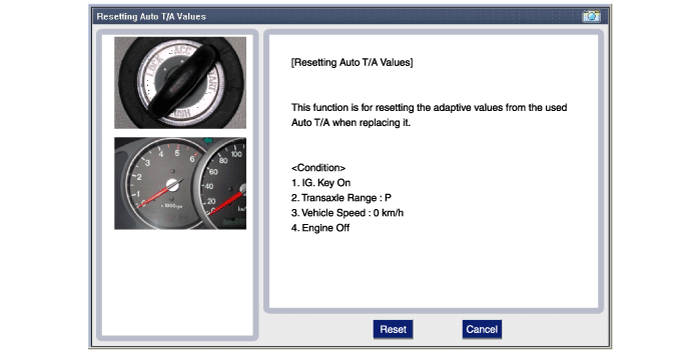
Reset the automatic transaxle adaptive values using the GDS.
Perform the TCM adaptive values learning procedure.
(Refer to Automatic Transaxle Control System - "Repair procedures")
