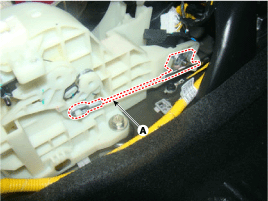
Remove the shift lock cable (A).
Tightening torque:
8.8 ~ 13.7 N.m (0.9 ~ 1.4 kgf.m, 6.5 ~ 10.1 lb-ft)

Remove the center console.
(Refer to "interior(console)"in BD group)
Remove the shift lock cable (A).
Tightening torque:
8.8 ~ 13.7 N.m (0.9 ~ 1.4 kgf.m, 6.5 ~ 10.1 lb-ft)

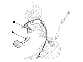
Remove the shift lock cable (B) from the brake pedal (A).

Installation is the reverse of removal.
Shift lock cable must be free unreasonable bending.
Assemble method of shift lock control cable
Connect shift lock cable to brake pedal and fix cable end to pin of pedal arm with snap pin.
Keep the brake pedal in initial position(undepressed position) while shift lock cable assembled.
Set lever to "P" position
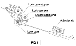
Assemble shift lock cable to lever as FIG 1, temporarily and cable end must be inserted into pin of lock cam securely.
Maintaining close touched state between lock cam and lock cam stopper, pull outor casing of shift lock cable in direction "E" slightly to remove slack of shift lock cable.
After checking that cable end is touched to pin of lock cam, fix the adjust plate by nut with specified torque.
Check that cable end is touched to pin of lock cam.

Check the shift lock function
Shift lever must not be shifted from "P" position to "R" position with brake pedal being not depressed.
Shift lever must not be be shift from "N" position to "R" position with brake pedal being not depressed.(Gate type only)
Shift lever can be smoothly from eatch position to other position with brake pedal being depressed by strocke 12~16mm.
Brake pedal must be operated smoothly without interruption at all positions.