2.
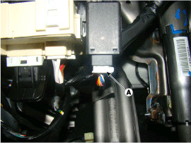
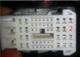
Disconnect the SSEM connector (A).
Mount the test fuse to the switch fuse and relay fuse part to confirm a normal joint fit.
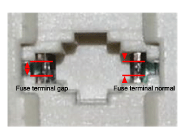
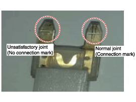
Check to see whether or not each connector has been damaged, or terminal surge, or incomplete connection has taken place
[Engine room junction box]
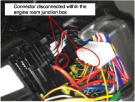
[Stop signal electronic module]
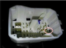
[ABS/VDC control module]
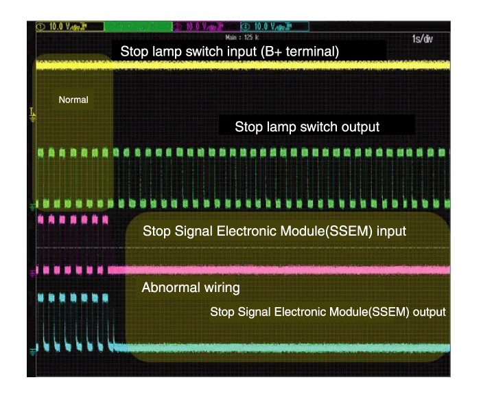
Connect probe to each terminal wire and confirm oscilloscope waveform.
[Stop lamp switch input/output]
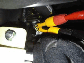
[Stop signal electronic module input/output]
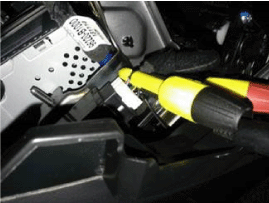
[Oscilloscope waveform screen]
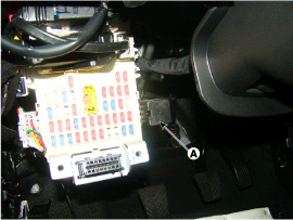
Turn ignition switch OFF and disconnect the negative (-) battery cable.
Disconnect the SSEM connector (A).

Remove the SSEM (A).
Installation is the reverse of removal.