4.
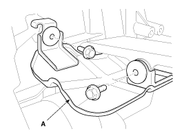
Disconnect the cable assembly (C) after removing the clips (B) and pins (A).
caution
The clips use new one.

Remove the air cleaner assembly.
(Refer to Engine Mechanical System - "Air Cleaner Assembly")
Remove the Battery and tray.
(Refer to Engine Electrical System - "Battery")
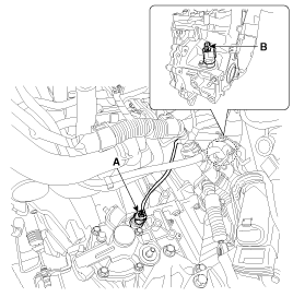
Remove the ECM.
(Refer to Engine Control System - "ECM")
Disconnect the cable assembly (C) after removing the clips (B) and pins (A).
The clips use new one.
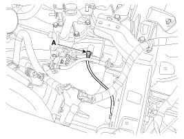
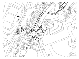
Disconnect the back up lamp switch connector (A) and the vehicle speed sensor connector (B).
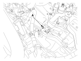
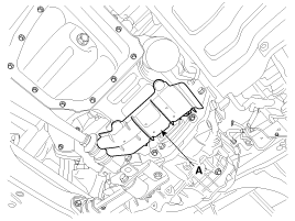
Remove the ground cable from transaxle (A).
Remove the tube bracket bolt (A).
Tightening torque:
14.7 ~ 21.6 N.m (1.5 ~ 2.2 kgf.m, 10.8 ~ 15.9 lb-ft)
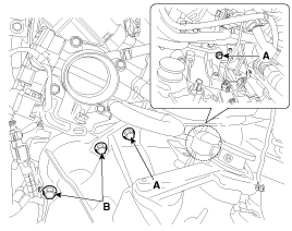
Remove the transaxle upper mounting bolt (A-2ea) and the start motor mounting bolt (B-2ea).
Tightening torque:
(A) 42.2 ~ 54.0 N.m(4.3 ~ 5.5 kgf.m, 31.1 ~ 39.8 lb-ft)
(B) 38.2 ~ 58.8 N.m (3.9 ~ 6.0 kgf.m, 28.2 ~ 43.4 lb-ft)
Remove the cowl top cover.
(Refer to Body - "Cowl Top Cover")
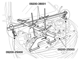
Assemble the engine support fixture(beam No.: 09200-38001 or 09200-3N000, supporter No.: 09200-2S000)
Refer to Special Service Tools - "Engine support fixture assembly drawing")
Using the engine support fixture assembly, hold the engine and transaxle assembly safely.
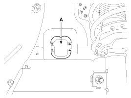
Remove the mounting cover (A).
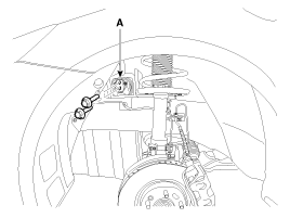
Remove the transaxle support mounting bracket bolts (A-2ea).
Tightening torque:
88.3 ~ 107.9 N.m (9.0 ~ 11.0 kgf.m, 65.1 ~ 79.6 lb-ft)
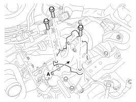
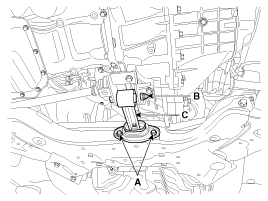
Remove the transaxle support bracket bolts (A-3ea).
Tightening torque:
58.9 ~ 78.5 N.m (6.0 ~ 8.0 kgf.m, 43.4 ~ 57.9 lb-ft)
Remove the under cover.
(Refer to Engine Mechanical System - "Engine Room Under Cover")
Remove the drive shaft assembly.
(Refer to "Driveshaft and axle - "Drive shaft assembly")
Remove the heater protector (A) after removing the bolts.
Remove the clutch release cylinder assembly (B) after removing the nuts (A-2ea).
Remove the brackets (A).
Remove the roll rod bracket (C) after removing bolt (A,B).
Tightening torque:
(A) 49.0 ~ 63.7 N.m (5.0 ~ 6.5 kgf.m, 36.2 ~ 47.0 lb-ft)
(B) 107.9 ~ 127.5 N.m (11 ~ 13 kgf.m, 79.6 ~ 94.1 lb-ft)
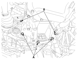
Remove the mounting bolts (A-3ea, B-2ea) of lower part of the transaxle, and the left side cover and remove the transaxle assembly by supporting it with a jack.
Be careful not to damage other system or parts near by when removing the engine and transaxle assembly.
Tightening torque:
(A) 42.2 ~ 48.1 N.m (4.3 ~ 4.9 kgf.m, 31.1 ~ 35.4 lb-ft)
(B) 42.2 ~ 53.9 N.m (4.3 ~ 5.5 kgf.m, 31.1 ~ 39.8 lb-ft)
Install in the reverse order of removal.
If the oil seal on the transaxle case side is damaged and fluid is leaking, replace the oil seal with a new unit. When installing the new oil seal, use the specialized tool (oil seal installer, 09452-1P100).
Add manual transaxle fluid.
(Refer to Manual Transaxle System - "Manual Transaxle Fulid")
