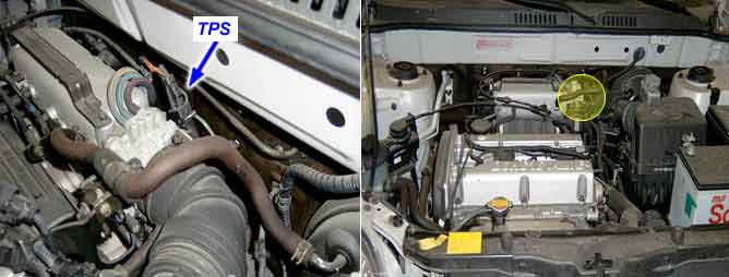
Throttle Position (TP) Sensor measures the opening angle of throttle valve and mounts on the side of the throttle body and is connected to the throttle blade shaft. The TP sensor’s resistance changes according to the throttle blade shaft position. TP Sensor has a potentiometer whose resistance changes along with the Throttle valve position. The Engine Control Module (ECM) provides a 5volt reference voltage to the TP Sensor. The ECM reads the voltage across the TP Sensor and converts it into throttle position. During acceleration, the TP Sensor resistance decreases. During deceleration, the TP Sensor resistance increases. The ECM uses the TP Sensor signal to adjust timing and injector pulse width. The TP Sensor signal along with the MAF sensor signal is used by the ECM to calculate engine load. Throttle angle information to the ECM to be used for the detection of engine status such as idle, part load, full throttle condition and anti-jerk condition and acceleration fuel enrichment correction.
If TPS output voltage is lower than 0.2 V, the ECM judged as low voltage and DTC is set.
Item | Detecting Condition | Possible cause |
DTC Strategy | ● Output voltage is monitored. | ● Poor connection ● Open or short to ground in TPS circuit ● Defective TPS ● Defective ECM |
Enable Conditions | ||
Threshold value | ● Output voltage, VTPS < 0.2V | |
Diagnosis Time | ● Continuous | |
MIL On Condition | ● 2 driving cycles |
During acceleration, the TPS output voltage increases; during deceleration, the TPS output voltage decreases. As much as possible, TPS signal should be compared with the MAP signal. And check whether TPS and MAP signals are increased at the same time when accelerated.