3.
ARE THE WIRES O.K ? & ARE THE CONNECTIONS O.K ?
YES
a.
Go to "Signal Circuit Inspection" procedure
NO
a.
Repair as necessary and go to " Verification of Vehicle Repair " procedure
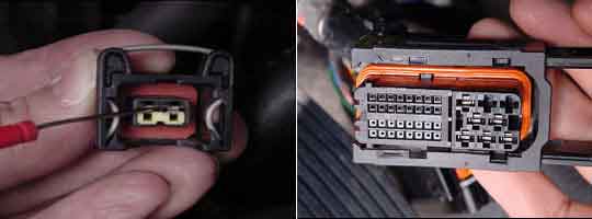
Check for damaged harness and terminals including rubber seals :
contact resistance, oxidation, corrosion, bent or broken terminals
harness connector connection, loose wires etc.
Check for poor connection between ECM and component :
backed out terminal, improper mating, broken locks and poor terminal to wire connection
ARE THE WIRES O.K ? & ARE THE CONNECTIONS O.K ?
YES
Go to "Signal Circuit Inspection" procedure
NO
Repair as necessary and go to " Verification of Vehicle Repair " procedure
DTCs listed below are stored in the scan tool
P1112/C018_C019_C029
Check items with the scan tool and the multimeter
① Wiring harness inspection
② Battery voltage from fuse B+ (15A)
③ Waveform from the VGT sol. Valve
Specification
Resitance : below 1 Ω for open in the wire
Resitance : infinite for short to ground in the wire
Voltage : below 0.5V for short to power in the wire
Reference voltage approx. 12V from fuse B+ (15A)
Resitance : 14 - 17 Ω at 20℃(68℉)
Refer to the component and full circuit for connector configrations details
Disconnect the VGT sol. valve and turn the ignition switch ON.
measure the voltage for the VGT sol. valve terminal 1 and terminal 2
ARE THERE A BATTERY VOLTAGE ?
YES
Go to step 4
NO
Go to step 3
ARE THE FUSES BLOWN ?
YES
Repair short in the wire between the VGT sol. valve terminal 2 and the fuse B+ (15A)
Repair short in the wire between the VGT sol. valve terminal 1 and the ECM terminal 24/C230-1
Replace the fuse if the fuse is broken
Go to step 4
NO
Go to step 4
Connect the VGT sol. valve and turn the ignition switch ON
measure the voltage terminal 1 and terminal 2
ARE THERE A BATTERY VOLTAGE ?
YES
Go to step 9
NO
Replace the VGT sol. Valve
For checking the VGT sol. valve , Go to "Component Inspection" procedure.
Start the engine and check the signal wavform at the VGT sol. valve terminal 2 ?
IS THERE THE SIGNAL WAVEFORM PROPERLY DISPLAYED ?
YES
Go to "Verification of Vehicle Repair" procedure
NO
Go to step 8
WAVEFORM ANALYSIS
This test should be inspected after depressing the HOLD mode at the operating range of VGT sol.valve.
The time T becomes shorter when the VGT sol. valve is opened increasingly.
If the rectangular waveform pattern is distorted and omitted, replace the VGT sol. valve.
Start the engine and check the signal wavform at the ECM terminal 24/C230-1 directly.
IS THERE THE SIGNAL WAVEFORM (DUTY 75%) PROPERLY DISPLAYED ?
YES
Go to "Verification of Vehicle Repair" procedure
NO
Replace a known - good ECM and recheck. If normal wavefoam is displayed, replace the ECM.
Disconnect the VGT sol. valve and turn the ignition switch ON.
measure the voltage for the VGT sol. valve terminal 1 and terminal 2.
ARE THERE A BATTERY VOLTAGE ?
YES
Go to step 4
NO
Go to step 3
ARE THE FUSES BLOWN ?
YES
Repair open or short in the wire between the VGT sol. valve terminal 2 and the fuse B+ (15A)
Repair open or short in the wire between the VGT sol. valve terminal 1 and the ECM terminal 24/C230-1
Replace the fuse if the fuse is broken
Go to step 4
NO
Go to step 4
Connect the VGT sol. valve and turn the ignition switch ON
measure the voltage terminal 1 and terminal 2
ARE THERE A BATTERY VOLTAGE ?
YES
Go to step 9
NO
Replace the VGT sol. Valve
For checking the VGT sol. valve , Go to "Component Inspection" procedure.
Start the engine and check the signal wavform at the VGT sol. valve terminal 2 ?
IS THERE THE SIGNAL WAVEFORM PROPERLY DISPLAYED ?
YES
Go to "Verification of Vehicle Repair" procedure
NO
Go to step 8
WAVEFORM ANALYSIS
This test should be inspected after depressing the HOLD mode at the operating range of VGT sol.valve.
The time T becomes shorter when the VGT sol. valve is opened increasingly.
If the rectangular waveform pattern is distorted and omitted, replace the VGT sol. valve.
Start the engine and check the signal wavform at the ECM terminal 24/C230-1 directly.
IS THERE THE SIGNAL WAVEFORM PROPERLY DISPLAYED ?
YES
Go to "Verification of Vehicle Repair" procedure
NO
Replace a known - good ECM and recheck. If normal wavefoam is displayed, replace the ECM.
If the C 029 is stored in the scan tool, the engine or A/T symptoms will occur as follows :
① Engine performance reduction
② Black smoke
③ Gear shifting failure
Prior to the DTC troubleshooting procedure, go to "Component Inspection" procedure
Go to "Verification of Vehicle Repair" procedure
After completing the component inspection procedure.
