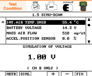
IS THE IATS SIGNAL CHANGED PROPERLY ACCORDING TO THE SIMULATION OF VOLTAGE ?
YES
Go to step 8
NO
Recheck open or short in the wire between the MAFS terminal 5 and the ECM terminal 5/C230-2.
Go to step 6

Connect the scan tool to the data link connector(DLC) and start the engine
Go to SIMU-SCAN
Fix the intake air temperature current data for the voltage simulation
- For SIMU-SCAN function information, Go to "Component Inspection" procedure
Apply the simulation voltage to the MAFS terminal 5 directly.
IS THE IATS SIGNAL CHANGED PROPERLY ACCORDING TO THE SIMULATION OF VOLTAGE ?
YES
Go to step 8
NO
Recheck open or short in the wire between the MAFS terminal 5 and the ECM terminal 5/C230-2.
Go to step 6

Apply the simulation voltage to the ECM teminal 5/C230-2 directly.
IS THE IATS SIGNAL CHANGED PROPERLY ACCORDING TO THE SIMULATION OF VOLTAGES ?
YES
Go to step 8
NO
Replace a known - good ECM and if normal IATS readings are indicated, replace the ECM
Go to step 8
HFM5/4.7 WITH AIR TEMPERAURE SENSOR
Temperature [℃] | Resistance [Ω] Min | Resistance [Ω] Typ. | Resistance [Ω] Max |
-40 (-40℉) | 35,140 | 39,260 | 43,760 |
-30 (-22℉) | 20,770 | 22,960 | 25,310 |
-20 (-4℉) | 12,660 | 13,850 | 1,5120 |
-10 (14℉) | 7,943 | 8,609 | 9,307 |
0 (32℉) | 5,119 | 5,409 | 5,892 |
10 (50℉) | 3,384 | 3,604 | 3,829 |
20 (68℉) | 2,290 | 2,420 | 2,551 |
30 (86℉) | 1,573 | 1,662 | 1,752 |
40 (104℉) | 1,096 | 1,166 | 1,238 |
50 (122℉) | 779 | 835 | 892 |
60 (140℉) | 565 | 609 | 654 |
70 (158℉) | 416 | 451 | 488 |
80 (176℉) | 312 | 340 | 370 |
90 (194℉) | 238 | 261 | 285 |
100 (212℉) | 184 | 202 | 222 |
110 (230℉) | 144 | 159 | 176 |
120 (248℉) | 114 | 127 | 141 |
130 (266℉) | 91 | 102 | 114 |
There is a signal voltage or a output value difference due to the contact resistnace or any other reasons between the probe and the sensor terminal.
Perform the test drive
MONITORING FOR PENDING DTC SET ?
YES
Go to the applicable troubleshooting procedure.
NO
System OK