7.
TCS failure
Inhibit the TCS control and allow the ABS/EBD control. Meanwhile, stop checking the TCS switch failure under the TCS control.
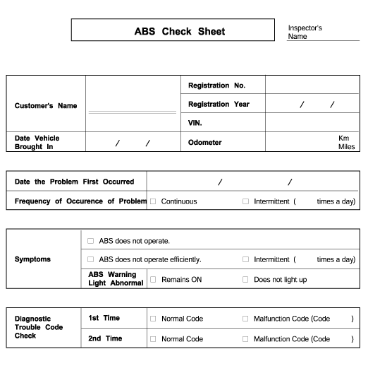
* Using the customer problem analysis check sheet for reference, ask the customer as much detail as possible about the problem. |
Phenomenon | Explanation |
System check sound | |
ABS operation sound | 1. Sound of the motor inside the ABS hydraulic unit operation (whine). 2. Sound is generated along with vibration of the brake pedal (scraping). 3. When ABS operates, sound is generated from the vehicle chassis due to repeated brake application and release (Thump : suspension; squeak: tires) |
ABS operation (Long braking distance) | For road surfaces such as snow-covered and gravel roads, the braking distance for vehicles with ABS can sometimes be longer than that for other vehicles. Accordingly, advise the customer to drive safely on such roads bylowering the vehicle speed. |
Pedal kick back | Pedal kick back is normal operation. |
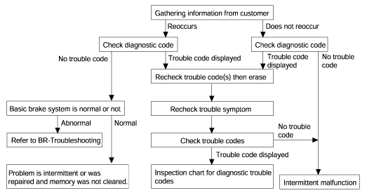
Diagnosis detection conditions can vary depending on the diagnosis code. When checking the trouble symptom after the diagnosis code has been erased,ensure that the requirements listed in "Comment" are met. | |
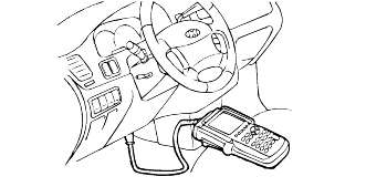
Turn the ignition "OFF".
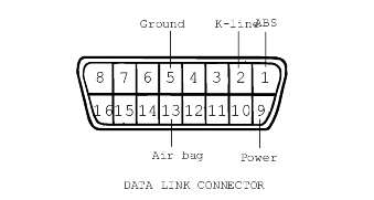
Connect the Hi-scan to the data link connector located underneath low crash pad panel.
Turn the ignition "ON".
Use the Hi-scan to check the self-diagnosis codes.
After completion of the repair or correction of the problems, turn the ignition switch; then erase the stored faults codes using the clear key.
Disconnect the Hi-scan.
No. | Description | Condition | Recognition | Time |
01 | Motor | KEY ON ENG. OFF | Motor pump relay operation (Click sounds) | 2 seconds |
02 | Front left valve (In) | Front left solenoid valve operation (Click sounds) | ||
03 | Front right valve (In) | Front right solenoid valve operation (Click sounds) | ||
04 | Rear left valve (In) | Rear left solenoid valve operation (Click sounds) | ||
05 | Rear right valve (In) | Rear right solenoid valve operation (Click sounds) | ||
06 | Front left valve (Out) | Front left solenoid valve operation (Click sounds) | ||
07 | Front right valve (Out) | Front right solenoid valve operation (Click sounds) | ||
08 | Rear left valve (Out) | Rear left solenoid valve operation (Click sounds) | ||
09 | Rear right valve (Out) | Rear right solenoid valve operation (Click sounds) |
No. | Description | Recognition | Unit |
1 | Battery | Battery | Voltage |
2 | FL wheel speed SNSR | Front left wheel speed sensor | km/h |
3 | FR wheel speed SNSR | Front right wheel speed sensor | |
4 | RL wheel speed SNSR | Rear left wheel speed sensor | |
5 | RR wheel speed SNSR | Rear right wheel speed sensor | |
6 | ABS SRI status | Warning lamp | ON/OFF |
7 | Brake SW | Brake switch | |
8 | Motor pump relay | Motor relay | |
9 | Valve relay | Valve relay | |
10 | Motor pump status | Motor | |
11 | FL valve (In) | Front left valve (In) | |
12 | FR valve (In) | Front right valve (In) | |
13 | RL valve (In) | Rear left valve (In) | |
14 | RR valve (In) | Rear right valve (In) | |
15 | FL valve (Out) | Front left valve (Out) | |
16 | FR valve (Out) | Front right valve (Out) | |
17 | RL valve (Out) | Rear left valve (Out) | |
18 | RR valve (Out) | Rear right valve (Out) |
DTC | Trouble Location | Remarks | |
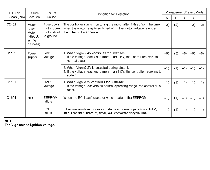
C1101 | Battery voltage over volt | : 18V or more | |
C1102 | Battery voltage low volt | : 9.5V or less | |
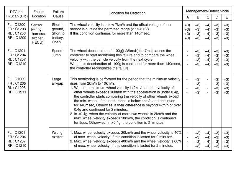
C1200 | FL wheel sensor | : open or short to ground | |
C1201 | - Range/Performance | : speed jump or damaged exciter | |
C1202 | - No signal | : air-gap error or wrong excite | |
C1203 | FR wheel sensor | : open or short to ground | |
C1204 | - Range/Performance | : speed jump or damaged exciter | |
C1205 | - No signal excite | : air-gap error or wrong excite | |
C1206 | RL wheel sensor | : open or short to ground | |
C1207 | - Range/Performance | : speed jump or damaged exciter | |
C1208 | - No signal excite | : air-gap error or wrong excite | |
C1209 | RR wheel sensor | : open or short to ground | |
C1210 | - Range/Performance | : speed jump or damaged exciter | |
C1211 | - No signal | : air-gap error or wrong excite | |
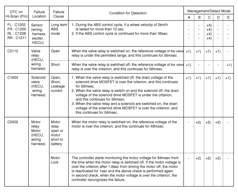
C1604 | ECU hardware | : ECU internal or valve failure | |
C2112 | Valve relay | : valve relay or fuse failure | |
C2402 | Motor-Electrical | : open or short to battery, motor relay, fuse or motor lock fail | |
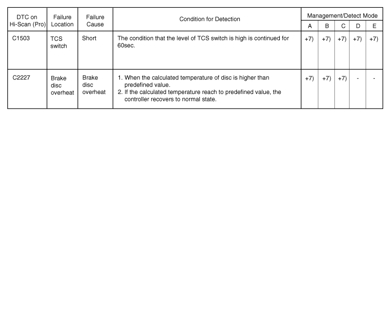
C2227 | Brake disc overheat | Only TCS | |
C1503 | TCS switch failure | With TCS switch | |
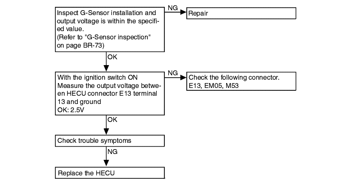
C1274 | G-sensor | : G-sensor signal failure | Only 4WD |
C1275 | G-sensor | : open or short to ground | Only 4WD |
DTC No. C1274 G-Sensor signal fail (Only 4WD) | Probable cause |
● Malfunction of G-Sensor. ● Malfunction of wiring harness or connector. ● Malfunction of HECU |
DTC No. C1275 G-Sensor open or short to ground (Only 4WD) | Probable cause |
This code is output when the voltage of G-Sensor signal is over 4.5V or under 0.6V. An open or short circuit is present in the G-sensor circuit. | ● Malfunction of G-Sensor. ● Malfunction of wiring harness or connector. ● Malfunction of HECU |
Trouble system | Inspection procedure No. | |
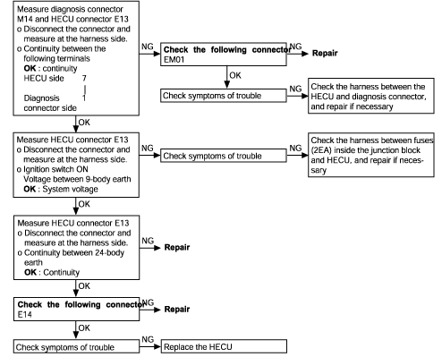
Communication with Hi-Scan (Pro) is not possible | Communication with any system is not possible. | 1 |
Communication with ABS only is not possible. | 2 | |
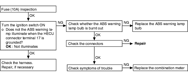
When the ignition key is turned to "ON" (engine OFF), the ABS warning lamp does not illuminate. | 3 | |
After the engine starts, the lamp remains illuminated. | 4 | |
Faulty ABS operation | Unequal braking power on both sides | 5 |
Insufficient braking power | ||
ABS operates under normal braking conditions | ||
ABS operates before vehicle stops under normal braking conditions | ||
Large brake pedal vibration (See Caution) | - | |
During ABS operation, the brake pedal may vibrate or may not be able to be depressed. Such phenomena are due to intermittent changes in hydraulic pressure inside the brake line to prevent the wheels from locking and is notan abnormality.
Communication with Hi-Scan is not possible. (Communication with all systems is not possible.) | Probable cause |
● Malfunction of connector ● Malfunction of wiring harness |
Communication with Hi-Scan is not possible. (Communication with ABS only is not possible.) | Probable cause |
● Blown fuse ● Malfunction of wiring harness or connector ● Malfunction of HECU |
When ignition key is turned "ON" (engine OFF), the ABS warning lamp does not illuminate | Probable cause |
● Blown fuse ● Burnt out ABS warning lamp bulb ● Malfunction of wiring harness or connector. ● Malfunction of active warning lamp module. ● Malfunction of HECU. |
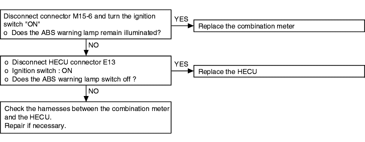
Even after the engine is started, the ABS warning lamp remains illuminated | Probable cause |
● Malfunction of combination meter ● Malfunction of HECU ● Malfunction of wiring harness |
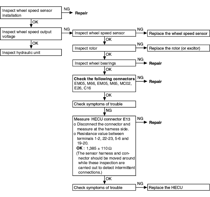
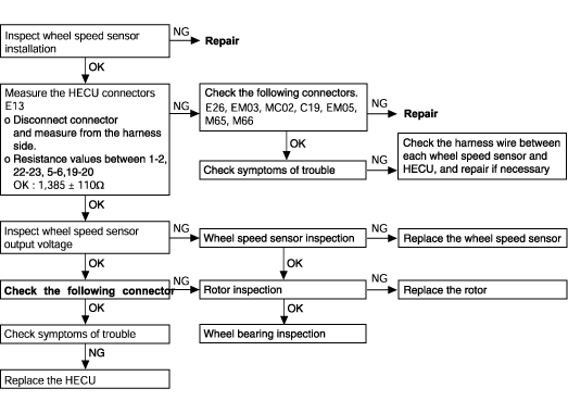
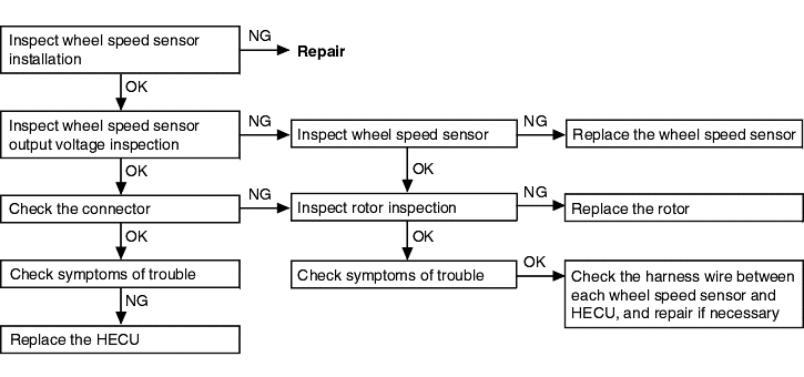
Brake operation is abnormal | Probable cause | |
● Improper installation of wheel speed sensor ● Incorrect sensor harness contact ● Foreign material adhering to wheel speed sensor | ● Malfunction of wheel speed sensor ● Malfunction of rotor ● Malfunction of wheel bearing ● Malfunction of hydraulic unit ● Malfunction of HECU |
System down. Both the ABS (TCS) and the EBD function are inhibited and the ABS (TCS) and the EBD warning lamps are activated.
If this happens, the valve relay and all solenoids are prevented from being switched on.
Only the ABS (TCS) function is inhibited. The ABS (TCS) warning lamp is activated and the EBD warning lamp is not activated.
Sensor failure outside the ABS control cycle.
Only one sensor fails : take the same action as management 2.
More than two sensors fail : take the same action as management 1.
Sensor failure inside the ABS control cycle.
One front sensor fails : inhibit the ABS control of the failed-wheel and maintain ABS control of the normal wheels.
After the controller completes the ABS control, take the same action as in management 2.
One rear sensor fails : inhibit ABS control of both front wheels and the pressure of both rear wheels is decreased.
After the controller completes the ABS control, take the same action as in management 2.
More than two sensor fail : take the same action as in management 1.
Low operating voltage
Outside the ABS control cycle : inhibit the ABS (TCS) control of front wheels and allow ABS control of rear wheels, deactivating the motor.
The ABS (TCS) warning lamp is directly switched on.
When the voltage recovers to the normal operating range, enable the ABS function and the ABS (TCS) warning lamp is switched off and erases theerror code of low voltage.
Inside the ABS control cycle : inhibit the ABS control of the front wheels and allow the the ABS control of rear wheels, deactivating the motor.
The ABS (TCS) warning lamp is directly switched on and remains on. The error code is always stored.
Motor error during the ABS control cycle. Inhibit the ABS control of front wheels, allow ABS control of the rear wheels and ABS (TCS) warning lampis switched ON at the end of ABS control.
TCS failure
Inhibit the TCS control and allow the ABS/EBD control. Meanwhile, stop checking the TCS switch failure under the TCS control.
DTC No. C1200, C1203, C1206, C1209 Wheel speed sensor open or short to GND circuit | Probable cause |
● Malfunction of wheel speed sensor ● Malfunction of wiring harness or connector ● Malfunction of HECU |
DTC No. C1201, C1204, C1207, C1210 (Speed jump or wrong exciter) | Probable cause |
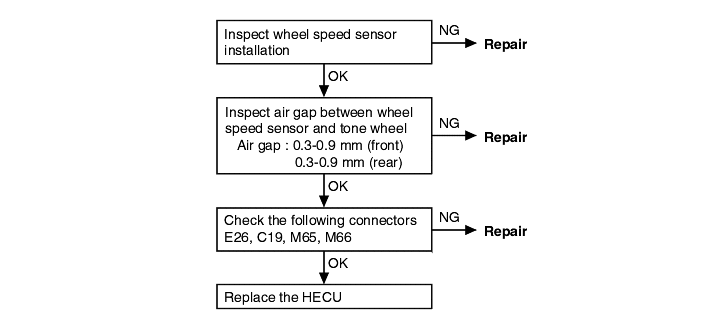
● Improper installation of wheel speed sensor ● Malfunction of wheel speed sensor ● Malfunction of rotor ● Malfunction of wheel bearing ● Malfunction of wiring harness or connector ● Malfunction of HECU |
DTC No. C1202, C1205, C1208, C1211 (Large air gap) | Probable cause |
A wheel speed sensor outputs no signal | ● Malfunction of wheel speed sensor ● Improper installation of wheel speed sensor ● Malfunction of rotor (excitor) ● Malfunction of wiring harness or connector ● Malfunction of HECU |
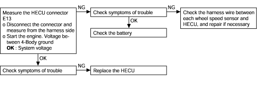
DTC No. C1101, C1102 Voltage out of range (Low and over voltage) | Probable cause |
● Malfunction of wiring harness or connector ● Malfunction of HECU. |
If battery voltage drops or rises during inspection, this code will be output as well. If the voltage returns to the standard value, the code is no longer output. Before carrying out the following inspection, check thebattery level and refill if necessary.
DTC No. C1604 ECU Hardware (EEPROM and ECU failure) | Probable cause |
● Malfunction of wiring harness ● Malfunction of hydraulic unit ● Malfunction of HECU |
DTC No. C2112 Valve relay (Including fuse failure) | Probable cause |
● Malfunction of wiring harness or connector ● Malfunction of HECU |
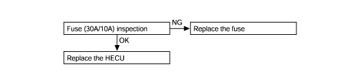
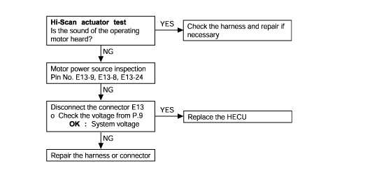
DTC No. C2402 Electrical (Motor relay, motor) | Probable cause |
● Malfunction of hydraulic unit ● Malfunction of HECU |
Because powering of the motor with the Hi-Scan or Hi-Scan Pro will discharge the battery, the engine should be run for a while after testingis completed.