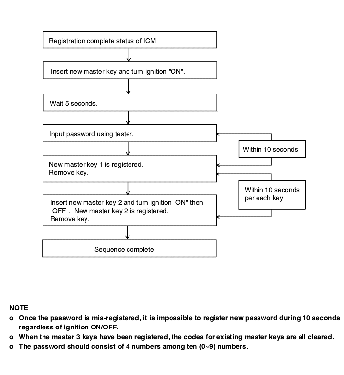
A. TRANSPONDER KEY
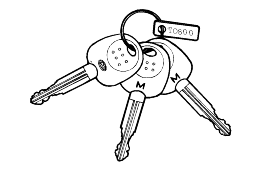
B. COIL ANTENNA
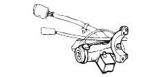
C. IMMOBILIZER CONTROL MODULE
D. ENGINE CONTROL MODULE
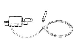
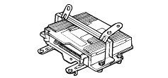
ICM : Immobilizer Control Module
ECM : Engine Control Module
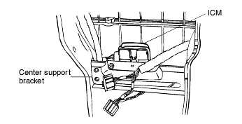
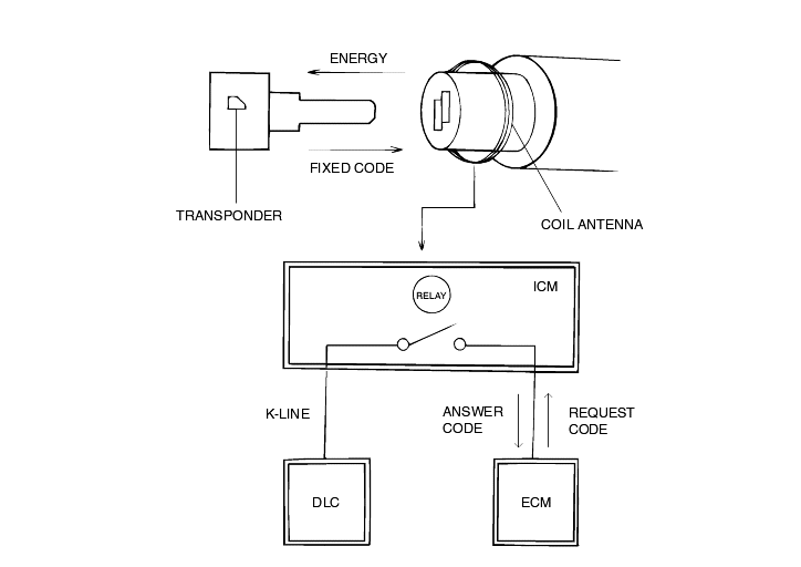
A. TRANSPONDER KEY | B. COIL ANTENNA |
 |  |
C. IMMOBILIZER CONTROL MODULE | D. ENGINE CONTROL MODULE |
 |  |
COMPONENT | DESCRIPTION | |
TRANSPONDER (built-in keys) | When ignition is "ON", the coil supplies energy to the transponder, which in turn accumulates energy in the condenser. Once the energy supply from the coil has stopped, using the stored energyin the condenser, the transponder transmits the ID CODE. | |
COIL ANTENNA | Supplies energy to the transponder. Receives signal from the transponder. Sends transponder signal to the ICM. | |
IMMOBILIZER CONTROL MODULE | Supplies power to the coil antenna. Receives and analyzes signal from the coil antenna. Transmits signal to ICM Stores VIN which composes of the ID CODE and password. | |
ENGINE CONTROL MODULE | With the ignition "ON", the ECM receives information from the ICM and permits injection to take place. | |
KEYS | ID KEY | Must be used first to register the unique ID CODE in the ICM. This ID CODE is then recorded into the master keys. |
MASTER | Once the ID CODE is recorded into the MASTER KEY, this key is for general use. | |
DATA LINK CONNECTOR | By connecting the voltmeter or HI-SCAN, control module diagnostic code can be read. |
ID Code registration sequence
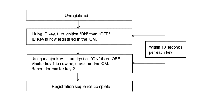
Master key correction
If a new set of master keys needs to be produced, it can be done by two methods:
Using ID key
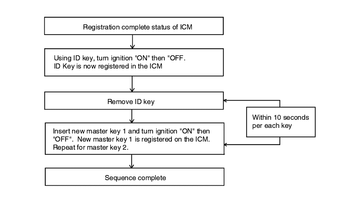
Using password
