The in-line fuel-injection pump's main area of application is still in all sizes of commercial-vehicle diesel engines, stationary diesel engines, locomotives and ships. Injection pressures of up to approx. 1350 bar are used to generate output powers of up to about 160 kW per cylinder.
Over the years, a wide variety of different requirements, such as the installation of direct-injection (DI) engines in small delivery vans and passenger cars, have led to the development of various diesel fuel-injection systems which are aligned to the requirements of a particular application. Of major importance in these developments are not only the increase in specificpower, but also the demand for reduced fuel consumption, and the call for lower noise and exhaust-gas emissions. Compared to conventional cam-driven systems, the Bosch "Common Rail" fuel-injection system for direct-injection (DI) diesel engines provides for considerably higher flexibility in the adaptation of the injection system to the engine, for instance :
Extensive area of application (for passenger cars and light commercial vehicles with output powers of up to 30kW/cylinder, as well as for heavy-duty vehicles, locomotives, and ships with outputs of up to approx. 200kW/cylinder,
High injection pressures of up to approx. 1400 bar.
Variable start of injection,
Possibility of pilot injection, main injection, and post injection,
Matching of injection pressure to the operating mode.
Pressure generation and fuel injection are completely decoupled from each other in the "Common Rail" accumulator injection system. The injection pressure is generated independent of engine speed and injected fuel quantity. The fuel is stored under pressure in the high-pressure accumulator (the "Rail") ready for injection. The injected fuel quantity is defined by the driver, and the start of injection and injection pressure are calculated by the ECU on the basis of the stored maps. The ECU then triggers the solenoid valves so that the injector (injection unit) at each engine cylinder injects accordingly. The ECU and sensor stages of such a CR fuel-injection system comprise :
ECU,
Crankshaft-speed sensor,
Camshaft-speed sensor,
Accelerator-pedal sensor,
Rail-pressure sensor,
Coolant sensor and
Air-mass meter.
Using the input signals from the above sensors, the ECU registers the driver's requirements (accelerator-pedal setting) and defines the instantaneous operating performance of the engine and the vehicle as a whole. It processes the signals which have been generated by the sensors and which it receives via data lines. On the basis of this information, it can then intervene with open and closed-loop controlling action at the vehicle and particularly at the engine. The engine speed is measured by the crankshaft-speed sensor, and the camshaft-speed sensor determines the firing sequence (phase length). The electrical signal generated across a potentiometer in the accelerator-pedal module informs the ECU about how far the driver has depressed the pedal, in other words about his (her) torque requirement.
The air-mass meter provides the ECU with data on the instantaneous air flow in order that combustion can be adapted so as to comply with the emissions regulations. Insofar as the engine is equipped with an exhaust-gas turbocharger and boost-pressure control, the boost-pressure sensor also measures boost-pressure. At low outside temperatures and with the engine cold, the ECU applies the data from the coolant-temperature and air-temperature sensors to adapt the setpoint values for start of injection, post injection, and further parameters to the particular operating conditions. Depending upon the vehicle in question, in order to comply with the increasing demands for safety and comfort, further sensors and data lines provide inputs to the ECU.
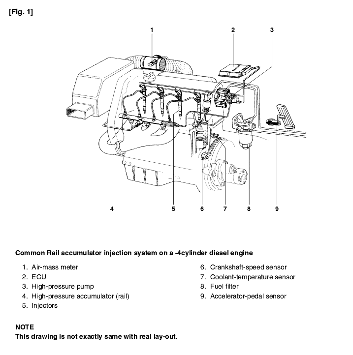
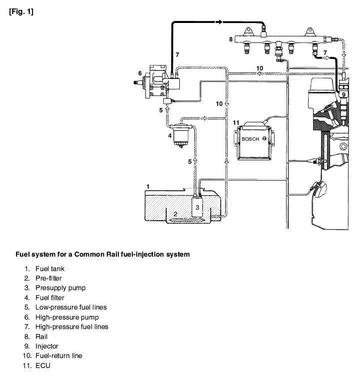
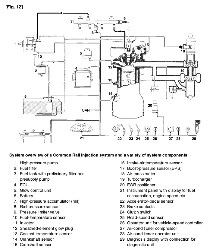
Fig. 1 shows an example of a 4-cylinder diesel engine fitted with a fuel-injection installation using the "Common Rail" accumulator injection system. Various components are shown.
The basic functions control the injection of the diesel fuel at the right moment, in the right quantities, and with the correct injection pressure. They ensure that the diesel engine not only runs smoothly, but also economically.
Auxiliary closed and open-loop control functions serve to improve both the exhaust-gas emission and fuel-consumption figures, or are used for increasing safety, comfort, and convenience. Examples here are Exhaust-Gas Recirculation (EGR), boost-pressure control, vehicle-speed control, and electronic immobilizer etc. The CAN bus system permits the exchange of data with other electronic systems in the vehicle. During vehicle inspection in the workshop, a diagnosis interface permits evaluation of the stored system data.
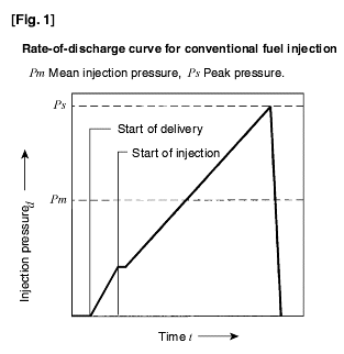
With conventional injection systems, using distributor and in-line injection pumps, fuel injection today comprises only the main injection phase - without pilot and post-injection phases (Fig. 1). On the solenoid-valve-controlled distributor pump though, developments are progressing towards the introduction of a pilot-injection phase. In conventional systems, pressure generation and the provision of the injected fuel quantity are coupled to each other by a cam and a pump plunger. This has the following effects upon the injection characteristics :
The injection pressure increases together with increasing speed and injected fuel quantity.
During the actual injection process, the injection pressure increases and then drops again to the nozzle closing pressure a the end of injection.
The consequences are as follows :
Smaller injected fuel quantities are injected with lower pressures than larger injected fuel quantities (refer to Fig. 1)
The peak pressure is more than double that of the mean injection pressure, and
In line with the requirements for efficient combustion, the rate-of discharge curve is practically triangular.
The peak pressure is decisive for the mechanical loading of a fuel-injection pump's components and drive. On conventional fuel-injection systems it is decisive for the quality of the A/F mixture formation in the combustion chamber.
Compared to conventional injection characteristics, the following demands are made upon an ideal injection characteristic:
Independently of each other, injected fuel quantity and injection pressure should be definable for each and every engine operating condition (provides more freedom for achieving ideal A/F mixture formation)
At the beginning of the injection process, the injected fuel quantity should be as low as possible (that is, during the ignition lag between the start of injection and the start of combustion).
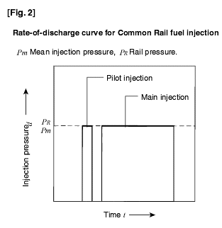
These requirements are complied with in the Common rail accumulator injection system with its pilot and main-injection features (Figs. 2 and 4)..
The Common Rail system is a modular system, and essentially the following components are responsible for the injection characteristic :
Solenoid-valve-controlled injectors which are screwed into the cylinder head,
Pressure accumulator (rail), and
High-pressure pump
The following components also also required in order to operate the system:
Electronic control unit (ECU),
Crankshaft-speed sensor, and
Camshaft-speed sensor (phases sensor).
For passenger-car systems, a radial-piston pump is used as the high-pressure pump for pressure generation. Pressure is generated independently of the injection process. The speed of the high-pressure pump is coupled directly to the enginespeed with a non-variable transmission ratio. In comparison with conventional injection systems, the fact that delivery is practically uniform, means that not only is the Common Rail high-pressure pump much smaller, but also that its drive is not subject to such high pressure-loading peaks.
The injectors are connected to the rail by short lines and, essentially, comprise a nozzle, and a solenoid valve which is energized by the ECU to switch it on (start of injection). When the solenoid valve is switched off (de-energized) injection ceases. Presuming constant pressure, the injected fuel quantity is directly proportional to the length of time the solenoid valve is energized. It is completely independent of the engine or pump speed (time-controlled fuel injection).
The required high-speed solenoid switching is achieved by using high voltages and currents. This means that the solenoid-valve triggering stage in the ECU must be designed accordingly.The start of injection is controlled by the angle-time control system of the EDC (Electronic Diesel Control). This uses a sensor on the crankshaft to register engine speed, and a sensor on the camshaft for phase detection (working cycle).
Pilot injection can be advanced by up to 90° crankshaft (90°ks) referred to TDC. If the start of injection occurs less than 40°ks BTDC, fuel can be deposited on the surface of the piston and the cylinder walls, and can lead to unwanted dilution of the lube-oil. With pilot injection, a small amount of diesel fuel (1...4 mm³) is injected into the cylinder to "precondition" the combustion chamber. Combustion efficiency can be improved as a result, and the following effects are achieved :
The compression pressure is increased slightly due to pilot reaction and partial combustion, this in turn leads to
The main-injection ignition delay being reduced, and
A reduction of combustion-pressure rise and of the combustion-pressure peaks (softer combustion).
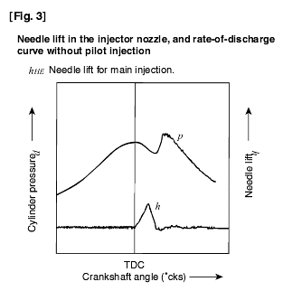
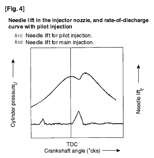
These effects reduce the combustion noise, the fuel consumption, and in many cases the exhaust-gas emissions as well. In the case of a rate-of-discharge curve without pilot injection (Fig. 3), in line with the compression only a slight, flat pressure rise is evident just before TDC, after which it peaks relatively sharply at the point of maximum pressure. The steep pressure increasetogether with the sharp peak contribute considerably to the diesel engine's combustion noise. As shown by the rate-of-discharge curve with pilot injection, (Fig. 4), pressure in the vicinity of TDC reaches a somewhat higher value, and the combustion-pressure increase is less rapid.
Since it reduces the ignition delay, pilot injection makes an indirect contribution to the generation of engine torque. The specific fuel consumption can increase or decrease as a function of the start of main injection and the time between the pilot and main injection sequences.
The energy for the engine's output work comes from the main injection sequence. This means that essentially the main injection is responsible for the development of the engine's torque. With the Common Rail accumulator fuel-injection system, the injection pressure remains practically constant throughout the whole of the injection process.
With certain versions of NOx catalytic converter, secondary injection can be applied for NOx combustion (reduction). It follows the main injection process and is timed to take place during the expansion or exhaust cycle up to 200캽ks after TDC. Secondary injection introduces a precisely metered quantity of fuel to the exhaust gas.
In contrast to the pilot and main injection processes, the injected fuel does not combust but instead vaporises due to the residual heat in the exhaust gas. During the exhaust cycle, the resulting mixture of exhaust gas and fuel is forced out through the exhaust valves and into the exhaust-gas system. Part of the fuel though is returned for combustion via the EGR system andhas the same effects as very advanced pilot injection. Provided suitable NOx catalytic converters are fitted, these utilise the fuel in the exhaust gas as a reduction agent to lower the NOx content in the exhaust gas.
Since very late secondary injection leads to dilution of the engine lube oil, it must be approved by the engine manufacture.
Compared to SI engines, diesel engines burn low-volatility (high-boiling) fuel, and not only prepare the air/fuel mixture in the period between injection and start of combustion, but also during the actual combustion process. The result is a less homogenous mixture. The diesel engine always operates with excess air (λ > 1). Fuel consumption, and the emissions of soot, CO, and HC increase if there is insufficient excess air. The A/F mixture formation is defined by the following parameters :
Injection pressure,
Rate of discharge (injection time),
Spray distribution (number of spray jets, spray cross-section, spray direction),
Start of injection,
Air movement, and
Air mass.
These quantities all have an effect upon the engine's emissions and fuel consumption. High combustion temperatures and high levels of oxygen concentration lead to increased NOx generation. Soot emissions rise due to lack of air and poor A/F mixture formation.
The configuration of the combustion chamber and air-intake tract can have a positive effect upon the exhaust-gas emissions. If the air movement in the combustion chamber is carefully matched to the fuel jets leaving the nozzle, this promotes efficient mixing of air and fuel and thus complete combustion of the injected fuel. In addition, positive effects are achieved with a homogenous mixture of air and exhaust gas and a cooled EGR tract. Four-valve techniques and turbochargers with variable-turbine geometry (VTG) also contribute to lower emissions and higher power density.
Without EGR, NOx emissions are excessive from the emission-control legislation standpoint, whereas soot emissions are within limits. Exhaust-gas recirculation (EGR) is a method for reducing the emissions of NOx without drastically increasing the engine's soot output. This can be implemented very efficiently with the CR system thanks to the excellent A/F mixture formation resulting from the high injection pressures. With EGR, a portion of the exhaust gases are diverted into the intake tract during part-load operation. This not only reduces the oxygen content, but also the rate of combustion and the peak temperature atthe flame front, with the result that NOx emissions drop. If too much exhaust gas is recirculated though (exceeding 40% of the intake air volume), the soot, CO, and HC emissions, as well as the fuel consumption rise due to the lack of oxygen.
Start of injection, rate-of discharge curve, and atomization of the fuel also have an influence upon fuel consumption and upon exhaust-gas emissions.
Due to lower process temperatures, retarded fuel-injection reduces the NOx emissions. But if it is too far retarded, HC emissions and fuel consumption increase, as do soot emissions under high loading conditions. If the start of injection deviates by only 1°ks (crankshaft) from the desired value, NOx emissions can increase by as much as 5%. Whereas a deviation of 2°ks in the advance (early) direction can lead to a 10 bar increase in the cylinder peak pressure, a deviation of 2°ks in the retarded (late) direction can increase the exhaust-gas temperature by 20°. Such high sensitivity demands utmost accuracy when adjusting the start of injection.
The rate-of discharge curve defines the variations in fuel mass flow during a single injection cycle (from start of injection till end of injection). The rate-of-discharge curve determines the mass of fuel delivered during the combustion lag (between start of injection and start of combustion). Furthermore, since it also influences the distribution of the fuel in the combustion chamberit also has an effect upon the efficiency of the air utilization. The rate-of-discharge curve must climb slowly in order that fuel injection during the combustion lag is kept to a minimum. This fuel, namely, combusts suddenly as soon as combustion is initiated with the attendant negative effects upon engine noise and NOx emissions. The rate-of-discharge curve must drop-off sharply in order to prevent poorly atomized fuel leading to high HC and soot emissions, and increased fuel consumption during the final phase of combustion.
Finely atomized fuel promotes the efficient mixing of air and fuel. It contributes to a reduction in HC and soot emissions. High injection pressure and optimal geometrical configuration of the nozzle injection orifices lead to good atomization. To prevent visible soot emission, the injected fuel quantity must be limited in accordance with the intake air quantity. This necessitates excess air in the order of at least 10...40% (λ=1.1 ...1.4). Once the nozzle needle has closed, the fuel in the injection orifices can vaporize (in the case of sac-hole (blind-hole) nozzles the fuel vaporizes in the sac-hole volume) and in the process increase the HC emissions. This means that such (harmful) volumes must be kept to a minimum.
The fuel system in a "Common Rail" fuel-injection system (Fig. 1) comprises a low-pressure stage for the low-pressure delivery of fuel, a high-pressure stage for the high-pressure delivery, and the ECU (11).
The low-pressure stage of the Common Rail fuel system incorporates :
Fuel tank with pre-filter,
Presupply pump,
Fuel filter, and
Low-pressure fuel lines.
As an alternative to steel pipes, flame-inhibiting steel-braid-armoured flexible fuel lines can be used for the low-pressure stage. They must be routed so that they cannot be damaged mechanically, and fuel which has dripped or evaporated must not be able to accumulate, nor must it be able to ignite. When the vehicle twists, or the engine moves etc., this must have no derogatory effects upon fuel-line function. All parts which carry fuel must be protected against the effects of heat. In the case of buses, fuel lines must not be located in the passenger compartment or in the driver's cab, nor may fuel be delivered by force of gravity.
The presupply pump is either an electric fuel pump with pre-filter, or a gear-type fuel pump. The pump draws the fuel from the fuel tank and continually delivers the required quantity of fuel in the direction of the high-pressure pump.
Inadequate filtering can lead to damage at the pump components, delivery valves, and injector nozzles. The fuel filter cleans the fuel before it reaches the high-pressure pump, and thereby prevents premature wear at the pump's sensitive components.
The high-pressure stage of the fuel system in a Common Rail installation comprises:
High-pressure pump with pressure-control valve,
High-pressure fuel lines,
The rail as the high-pressure accumulator with rail-pressure sensor, pressure-limiting valve, and flow limiter, injectors, and
Fuel-return lines.
The high-pressure pump pressurises the fuel to a system pressure of up to 1,350bar. This pressurized fuel then passes through a high-pressure line and into the tubular high-pressure fuel accumulator (rail).
Even after an injector has taken fuel from the rail in order to inject it, the fuel pressure inside the rail remains practically constant. This is due to the accumulator effect arising from the fuel's inherent elasticity. Fuel pressure is measured by the rail-pressure sensor and maintained at the desired level by the pressure-control valve.
The nozzles of these injectors open when the solenoid valve is triggered and permit the flow of fuel. They inject the fuel directly into the engine's combustion chamber. The excess fuel which was needed for opening the injector nozzles flows back to the tank through a collector line. The return fuel from the pressure-control valve and from the low-pressure stage is also led into this collector line together with the fuel used to lubricate the high-pressure pump.
These fuel lines carry the high-pressure fuel. They must therefore be able to permanently withstand the maximum system pressure and, during the pauses in injection, the sometimes high-frequency pressure fluctuations which occur. They are therefore manufactured from steel tubing. Normally, they have an outside diameter of 6 mm and an internal diameter of 2.4 mm. The injection lines between the rail and the injectors must all be of the same length. The differences in length between the rail and the individual injectors are compensated for by using slight or pronounced bends in the individual lengths of tubing.Nevertheless, the injection lines should be kept as short as possible.
The low-pressure stage (Fig. 1) provides enough fuel for the high-pressure section. The most important components are :
Fuel tank,
Pre-supply pump with prefilter,
Low-pressure fuel lines for supply and return,
Fuel filter and
Low-pressure area of the high-pressure pump.
It is the pre-supply pump's job to maintain an adequate supply of fuel to the high-pressure pump. This applies
In every operating state,
At the necessary pressure, and
Throughout the complete service life.
At present, there are two possible versions. An electric roller-cell fuel pump is the standard solution. An alternative is the mechanically driven gear-type fuel pump.
The electric fuel pump is only used in passenger cars and light commercial vehicles. It is not only responsible for delivering the fuel to the high-pressure pump, but within the framework of system monitoring it must also interrupt the flow of fuel in case of an emergency. Beginning with the engine cranking process, the electric fuel pump runs continuously independent of engine speed. This means that the pump permanently delivers fuel from the fuel tank, and through the filter to the high-pressure pump. Excess fuel can flow back to the tank through an overflow valve. A safety circuit is provided to prevent the delivery of fuel should the ignition be on with the engine stopped. Electric fuel pumps are available as in-line or in-tank versions. In-line fuel pumps are installed outside the tank in the fuel line between the tank and the fuel filter. They are attached to the vehicle's floor assembly. In-tank fuel-pump versions on the other hand are installed in the fuel tank itself using a special mounting. Apart from the electrical and hydraulic connections to the outside, this mounting usually incorporates a fuel strainer, a fuel-level indicator,and a swirl pot which acts as a fuel reservoir.

An electric fuel pump comprises the three function elements :
Pumping element,
Electric motor, and
End cover.
Contaminants in the fuel can lead to damage at the pump components, delivery valves, and injection nozzles. This, therefore, necessitates the use of a fuel filter which is specifically aligned to the requirements of the particular injection system, otherwise faultless operation and a long service life cannot be guaranteed. Diesel fuel can contain water either in bound form (emulsion)or in free form (e.g. condensation of water due to temperature change). If this water enters the injection system, it can lead to damage as a result of corrosion. Similar to other injection systems, the Common Rail also needs a fuel filter with water reservoir, from which the water must be drained at regular intervals. The increasing number of diesel engines used in passengercars, has led to the demand for an automatic water warning device which indicates by means of a warning lamp when water must be drained (this is binding in those countries in which there is a high level of water in the fuel).
In addition to high-pressure generation, fuel distribution and fuel-metering also take place in the high-pressure stage (Fig. 1). The most important components are :
High-pressure pump with element shutoff valve and pressure-control valve,
High-pressure accumulator,
Rail-pressure sensor,
Pressure-limiter valve,
Flow limiter and
Injectors.
High-pressure pump
The high-pressure pump (Figs. 7 and 8) is the interface between the low-pressure and the high-pressure stages. Under all operating conditions, it is responsible for providing adequate high-pressure fuel throughout the vehicle's complete service life. This also includes the provision of extra fuel as needed for rapid starting and for rapid build-up of pressure in the rail. The high-pressure pump continually generates the system pressure as needed in the high-pressure accumulator (rail). This means therefore, that in contrast to conventional systems, the fuel does not have to be specially compressed for each individualinjection process.
The high-pressure pump is installed preferably at the same point on the diesel engine as a conventional distributor pump. It is driven by the engine (at half engine speed, but max. 3000 min-1) through a coupling, gearwheel, chain, or toothed belt, and lubricated by the diesel fuel which it pumps. Depending on available space, a pressure-control valve is installed directly on thehigh-pressure pump or remote from it. Inside the high-pressure pump, the fuel is compressed with three radially arranged pump pistons which are at an angle of 120?to each other. Since three delivery stokes take place for every revolution, only low peak drive torques are generated so that the stress on the pump drive remains uniform. With 16Nm, the torque is only about 1/9 of that required to drive a comparable distributor pump. This means that Common Rail places less loading on the pump drive than is the case with conventional injection system. The power required to drive the pump climbs in proportion to the pressure set in the rail and to the pump's speed (delivery quantity). For a 2-liter engine turning at rated speed, and with a set pressure of 1,350 bar in the rail, the high-pressure pump requires 3.8kW presuming a mechanical efficiency of approx. 90%. The higher power demand (higher than theoretically necessary) results from the leak-fuel and control quantities at the injector, and from the fuel return through the pressure-control valve.
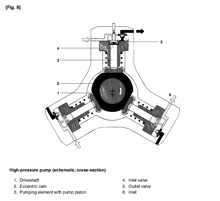
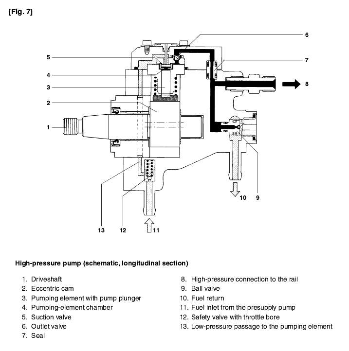
Via a filter with water separator, the presupply pump pumps fuel from the tank to the high-pressure pump through the fuel inlet (Fig. 7) and the safety valve. It forces the fuel through the safety valve's throttle bore and into the high-pressure pump's lubrication and cooling circuit. The driveshaft with its eccentric cams moves the three pump plungers up and down in accordance with the shape of the cam. As soon as the delivery pressure exceeds the safety valve's opening pressure (0.5 ... 1.5bar), the pre-supply pump can force fuel through the high-pressure pump's inlet valve into the pumping-element chamberwhose pump piston is moving downwards (suction stroke). The inlet valve closes when the pump piston passes through BDC and, since it is impossible for the fuel in the pumping-element chamber to escape, it can now be compressed beyond the delivery pressure. The increasing pressure opens the outlet valve as soon as the rail pressure is reached, and the compressed fuel enters the high-pressure circuit. The pump piston continues to deliver fuel until it reaches TDC (delivery stroke), after which the pressure collapses so that the outlet valve closes. The fuel remaining in the pumping-element chamber relaxes and the pump piston moves downwards again. As soon as the pressure in the pumping-element chamberdrops below the presupply- pump pressure, the inlet valve opens and the pumping process starts again.
Since the high-pressure pump is designed for large delivery quantities, excess high-pressure fuel is delivered during idle and part-load operation. This excess fuel is returned to the tank via the pressure-control valve. The compressed fuel relaxes in the tank, and the energy is lost which was used for compressing the fuel in the first place. In addition to the unnecessary heating up of the fuel, overall efficiency is also reduced. To a certain extent, this loss of efficiency can be compensated for by switching off one of the pumping elements.
The high-pressure pump's delivery rate is proportional to its rotational speed. And this, in turn, is a function of the engine speed. During the injection-system application-engineering work on the engine, the transmission ratio is defined so that on the one hand the amount of excess fuel is not too high, and on the other, the fuel requirements can still be satisfied during WOT operation. Referred to the crankshaft, transmission ratios of 1:2 and 2:3 are possible.
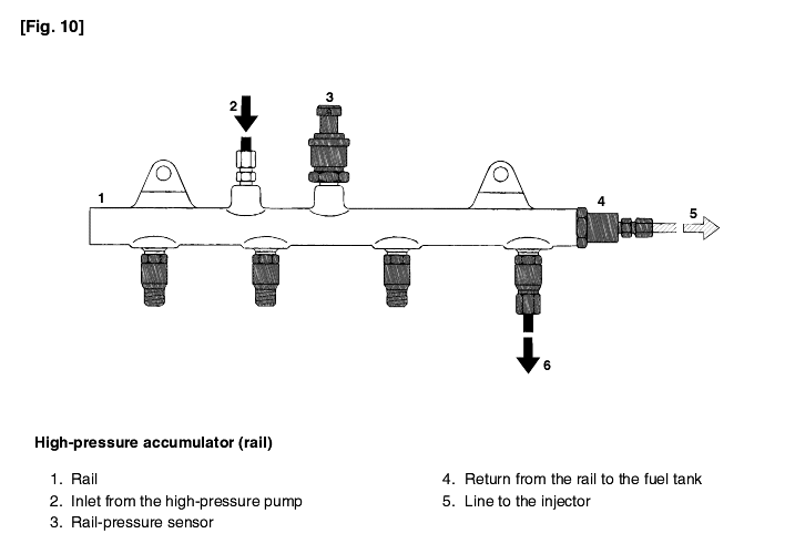
The high-pressure accumulator (the Rail in Fig. 10) stores the fuel at high pressure. At the same time, the pressure oscillations which are generated due to the high-pressure pump delivery and the injection of fuel are damped by the rail volume. This high-pressure accumulator is common to all cylinders, hence its name "common rail". Even when large quantities of fuel are extracted, the common rail maintains its inner pressure practically constant. This ensures that the injection pressure remains constant from the moment the injector opens.
In order to comply with the wide variety of engine installation conditions, the rail with its flow limiters and the provisions for attaching rail-pressure sensor, pressure-control valve, and pressure-limiter valve is available in a number of different designs.
The available rail volume is permanently filled with pressurized fuel. The compressibility of the fuel resulting from the high pressure is utilised to achieve the accumulator effect. When fuel leaves the rail for injection, the pressure in the high-pressure accumulator remains practically constant. Similarly, the pressure variations resulting from the pulsating fuel supply from thehigh-pressure pump are compensated for.
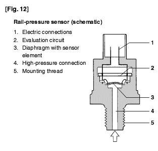
In order to output a voltage signal to the ECU which corresponds to the applied pressure, the rail-pressure sensor must measure the instantaneous pressure in the rail :
With adequate accuracy, and
As quickly as possible
The rail-pressure sensor (Fig. 12) comprises the following components :
An integrated sensor element welded to the pressure fitting,
A printed-circuit board (pcb) with electrical evaluation circuit, and
A sensor housing with electrical plug-in connection.
The fuel flows to the rail-pressure sensor through an opening in the rail, the end of which is sealed off by the sensor diaphragm. Pressurized fuel reaches the sensor's diaphragm through a blind hole. The sensor element (semiconductor device) for converting the pressure to an electric signal is mounted on this diaphragm. The signal generated by the sensor is inputted to an evaluation circuit which amplifies the measuring signal and sends it to the ECU.
The rail-pressure sensor (Fig. 12) operates as follows : When the diaphragm's shape changes, the electrical resistance of the layers attached to the diaphragm also change. The change in shape (approx. 1 mm at 1500bar) which results from the buildup of system pressure, changes the electrical resistance and causes a voltage change across the 5V resistance bridge. This voltage change is in the range 0 ... 70mV (depending upon the applied pressure) and is amplified by the evaluation circuit to 0.5 ... 4.5V. The precise measurement of rail pressure is imperative for correct system functioning. This is one of the reasons for the very tight tolerances which apply to the rail-pressure sensor during pressure measurement. In the main operating range, the measuring accuracy is approx. ± 2% of full-scale reading. If the rail-pressure sensor should fail, the pressure-control valve is triggered "blind" using an emergency (limp-home) function and fixed values.
The pressure limiter valve has the same job as an overpressure valve. In case of excessive pressure, the pressure limiter valve limits the rail pressure by opening an escape passage. The pressure limiter permits a short-time maximum rail pressure of 1500 bar.
The pressure-limiter valve is a mechanical device comprising the following components :
Housing with external thread for screwing to the rail,
A connection to the fuel-tank return line,
A movable plunger, and
A spring.
At the connection end to the rail, the housing is provided with a passage which is closed by the cone-shaped end of the plunger coming up against the sealing seat inside the housing. At normal operating pressures (up to 1350bar), a spring forces the plunger against the seat and the rail remains closed. As soon as the maximum system pressure is exceeded, the plunger is forced up by the rail pressure against the force of the spring. The fuel under high pressure can now escape, whereby it flows through passages into the plunger's interior from where it is led through a collector line back to the fuel tank. When the valve opens. fuel leaves the rail so that the rail pressure drops.
The start of injection and the injected fuel quantity are adjusted by electrically triggered injectors. These injectors supersede the nozzle-and-holder assembly (nozzle and nozzle-holder). Similar to the already existing nozzle-holder assemblies in direct-injection (DI) diesel engines, clamps are preferably used for installing the injectors in the cylinder head. This means that theCommon Rail injectors can be installed in already existing DI diesel engines without major modifications to the cylinder head.
The injector (Fig. 16) can be sub-divided into a number of function blocks:
The hole-type nozzle,
The hydraulic servo-system, and
The solenoid valve.
Referring to Fig. 16, fuel is fed from the high-pressure connection, to the nozzle through the passage, and to the control chamber through the feed orifice. The control chamber is connected to the fuel return via a bleed orifice which is opened by the solenoid valve.
With the bleed orifice closed, the hydraulic force applied to the valve control plunger exceeds that at the nozzle-needle pressure shoulder. As a result, the needle is forced into its seat and seals off the high-pressure passage from the combustion chamber.
When the injector's solenoid valve is triggered, the bleed orifice is opened. This leads to a drop in control-chamber pressure and, as a result, the hydraulic pressure on the plunger also drops. As soon as the hydraulic force drops below the force on the nozzle-needle pressure shoulder, the nozzle needle opens and fuel is injected through the spray holes into the combustion chamber. This indirect control of the nozzle needle using a hydraulic force-amplification system is applied because the forces which are necessary for opening the needle very quickly cannot be directly generated by the solenoid valve. The so-calledcontrol quantity needed for opening the nozzle needle is in addition to the fuel quantity which is actually injected, and it is led back to the fuel-return line via the control chamber's orifices.
In addition to the control quantity, fuel is also lost at the nozzle-needle and valve-plunger guides. These control and leak-off fuel quantities are returned to the fuel tank via the fuel return and the collector line to which overflow valve, high-pressure pump, and pressure-control valve and also connected.
The injector's operation can be subdivided into four operating states with the engine running and the high-pressure pump generating pressure :
Injector closed (with high pressure applied),
Injector opens (start of injection),
Injector opened fully, and
Injector closes (end of injection).
These operating states result from the distribution of the forces applied to the injector's components. With the engine at standstill and no pressure in the rail, the nozzle spring closes the injector.
In the at-rest state, the solenoid valve is not energized and is therefore closed (Fig. 16a). With the bleed orifice closed, the valve spring forces the armature's ball onto the bleed-orifice seat. The rail's high pressure builds up in the valve control chamber, and the same pressure is also present in the nozzle's chamber volume. The rail pressure applied at the control plunger's end face, together with the force of the nozzle spring, maintain the nozzle in the closed position against the opening forces applied to its pressure stage.
The injector is in its at-rest position. The solenoid valve is energized with the pickup current which serves to ensure that it opens quickly (Fig. 16b). The force exerted by the triggered solenoid now exceeds that of the valve spring and the armature opens the bleed orifice. Almost immediately, the high-level pick-up current is reduced to the lower holding current required for the electromagnet. This is possible due to the magnetic circuit's air gap now being smaller. When the bleed orifice opens, fuel can flow from the valve-control chamber into the cavity situated above it, and from there via the fuel return to the fuel tank, The bleed orifice prevents complete pressure balance, and the pressure in the valve control chamber sinks as a result. This leads to the pressure in the valve-control chamber being lower than that in the nozzle's chamber volume which is still at the same pressure level as the rail. The reduced pressure in the valve-control chamber causes a reduction in the force exerted on the control plunger, the nozzle needle opens as a result, and injection starts.
The nozzle needle's opening speed is determined by the difference in the flow rate through the bleed and feed orifices. The control plunger reaches its upper stop where it remains supported by a cushion of fuel which is generated by the flow of fuel between the bleed and feed orifices. The injector nozzle has now opened fully, and fuel is injected into the combustion chamber at a pressure almost equal to that in the fuel rail. Force distribution in the injector is similar to that during the opening phases.
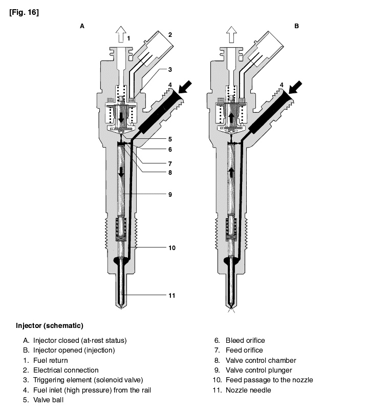
As soon as the solenoid valve is no longer triggered, the valve spring forces the armature downwards and the ball closes the bleed orifice. The armature is a 2-piece design. Here, although the armature plate is guided by a driver shoulder in its downward movement, it can "overspring" with the return spring so that it exerts no downwards-acting forces on the armature and the ball. The closing of the bleed orifice leads to pressure buildup in the control chamber via the input from the feed orifice. This pressure is the same as that in the rail and exerts an increased force on the control plunger through its end face. This force, together with that of the spring, now exceeds the force exerted by the chamber volume and the nozzle needle closes. The nozzle needle's closing speed is determined by the flow through the feed orifice. Injection ceases as soon as the nozzle needle comes up against its bottom stop again.
The Electronic Diesel Control (EDC) for Common Rail comprises three major system blocks :
Sensors and setpoint generators for registration of the operating conditions and the desired values. These convert a variety of physical parameters into electrical signals.
The ECU for generating the electrical output signals by processing the information using specified arithmetic operations (control algorithms)
Actuators to convert the ECU's electrical output signals into mechanical parameters.
The piston position in the combustion chamber is decisive in defining the start of injection. All the engine's pistons are connected to the crankshaft by connecting rods (conrods). A sensor on the crankshaft can therefore provide information on the position of all the pistons. The rotational speed defines the number of crankshaft rotations per minute. This important input variable is calculated in the ECU using the signal from the inductive crankshaft-speed sensor.
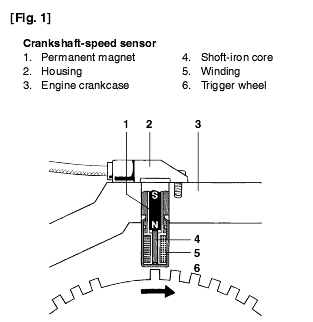
The camshaft controls the engine's intake and exhaust valves. It turns at half the speed of the crankshaft. When a piston travels in the directions of TDC, the camshaft position determines whether it is in the compression phase with subsequent ignition, or in the exhaust phase. The information cannot be generated from the crankshaft position during the starting phase. During normal engine operation on the other hand, the information generated by the crankshaft sensor suffices to define the engine status. In other words, this means that if the camshaft sensor should fail while the vehicle is being driven, the ECU still receives information on the engine status from the crankshaft sensor.
The camshaft sensor utilises the Hall effect when establishing the camshaft position. A tooth of ferromagnetic material is attached to the camshaft and rotates with it. When this tooth passes the semiconductor wafers of the camshaft sensor, its magnetic field diverts the electrons in the semiconductor wafers at right angles to the direction of the current flowing through the wafers. This results in a brief voltage signal (Hall voltage) which informs the ECU that cylinder 1 has just entered the compression phase.
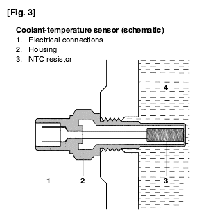
Temperature sensors are installed at a number of different points :
In the coolant circuit, to establish engine temperature by way of the coolant temperature (Fig. 3),
In the intake manifold to measure the temperature of the intake air,
In the engine lube oil to measure the oil temperature (optional), and
In the fuel-return line to measure the fuel temperature (optional).
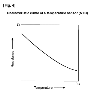
The sensors are equipped with a temperature-dependent resistor with a negative temperature coefficient (NTC) which is part of a voltage-divider circuit across which 5V are applied.
The voltage drop across the resistor is inputted into the ECU through an analog-to-digital converter (ADC) and is a measure for the temperature. A characteristic curve is stored in the ECU microcomputer which defines the temperature as a functionof the given voltage value (Fig. 4).
Particularly during dynamic operation, precise compliance with the correct A/F ratio is imperative in order to comply with the exhaust-gas limits as stipulated by law. This necessitates the use of sensors which precisely register the air-mass flow actually being drawn in by the engine at a particular moment. This load sensor's measuring accuracy must be completely independent of pulsation, reverse flow, EGR, variable camshaft control, and changes in the intake-air temperature.
A hot-film air-mass meter was selected as being most suitable for complying with the above stipulations. The hot-film principle is based on the transfer of heat from a heated sensor element to the air-mass flow (Fig. 5). A micromechanical measuring system is utilised which permits registration of the air-mass flow and detection of flow direction. Reverse flows are also detected in case of strongly pulsating air flow.
The micromechanical sensor element is located in the plug-in sensor's flow passage (Fig. 5,). The plug-in sensor can be installed in the air filter or in a measuring tube in the engine's air intake duct.
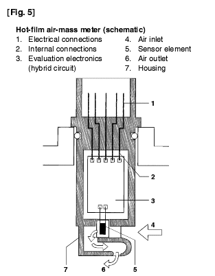
There are a variety of different-sized measuring tubes available, depending upon the maximum air throughput reqauired by the engine. The signal voltage curve, as a function of the air mass flow, is divided into signal ranges for forward flow and reverse flow. In order to increase measuring accuracy, the measuring signal is referred to a reference voltage outputted by the enginemanagement. The characteristic curve has been designed so that during diagnosis in the workshop and open circuit conductor, for instance, can be detected with the help of the engine management.
A temperature sensor can be incorporated for measuring the intake-air temperature.
In contrast to conventional distributor and in-line injection pumps, with EDC the driver's acceleration input is no longer transmitted to the injection pump by Bowden cable or mechanical linkage, but is registered by an accelerator-pedal sensor and transmitted to the ECU (this is also known as drive-by wire). A voltage is generated across the potentiometer in the accelerator-pedal sensor as a function of the accelerator-pedal setting. Using a programmed characteristic curve, the pedal's position is then calculated from this voltage.
The ECU evaluates the signals it receives from the external sensors and limits them to the permissible voltage level.
From this input data, and from stored characteristic maps, the ECU microprocessors calculate the injection times and the instants of injections, and convert these times to signal characteristics which are adapted to the movements of the engine pistons and crankshaft. The specified accuracy and the engine's high dynamic response demands high levels of computing power.
The output signals from the ECU microprocessors are used to trigger driver stages which provide adequate power for switching the actuators rail-pressuresure control and element switch-off. In addition, actuators for engine function are triggered (e.g. EGR actuator, and the relay for the electric fuel pump), as well as those for further auxiliary functions such as blower relay, auxilary-heater relays, glow relay, air-conditioner). The driver stages are proof against short-circuit and destruction due to brief electrical overloading. Errors of this type, and open-circuit or unplugged lines, are reported to the microprocessor.Diagnosis functions in the injector driver stages detect faulty signal characteristics, and in addition a number of the output signals are transferred via interfaces for use in other systems in the vehicle. And within the framework of a special safety concept, the ECU monitors the complete fuel-injection system.
Injector triggering places particularly heavy demands on the driver stages. In the injector, the current from the driver stage generates a magnetic force in the triggering element which is applied to the injector's high-pressure system. In order to ensure very tight tolerances, and high reproducibility of the injected fuel quantity, this coil must be triggered with steep current flanks. This necessitates high voltages being made available in the ECU.
A current control circuit divides the energisation time (injection time) into a pickup-current phase and a hold phase. It must operate so accurately that the injector guarantees reproducible injection under all operating conditions. In addition, it must reduce the power loss in the ECU and the injectors.
High demands are made upon the ECU regarding
The surrounding (ambient) temperatures (in normal cases from -40 ... +85°C),
The resistance to fuels and lubricants etc.,
The resistance to humidity, and
Mechanical loading.
Very high demands are also made upon electromagnetic compatibility (EMC) and upon the radiation of HF interference signals.
The ECU has a metal housing. The sensors, the actuators, and power supply are connected to the ECU through a multi-pole plug-in connector. The power components which directly trigger the actuators are integrated in the ECU in such a manner that they can efficiently dissipate their heat to the ECU housing. Both sealed and non-sealed versions of the ECU are available.
In order that the engine operates with optimum combustion in every operating state, the ECU in each case calculates the appropriate injected fuel quantity. In the process, a number of parameters must be taken into account (Fig. 6).
For starting, the injected fuel quantity is calculated as a function of temperature and cranking speed. The start quantity is injected from the moment the starting switch is turned to "Start" (Fig. 6, Pos. A) until the engine has reached a given minimum speed. The driver has no influence upon the start quantity.
When the vehicle is being driven normally (Fig. 6, stating switch in Pos. B), the injected fuel quantity is calculated from the accelerator-pedal setting (accelerator-pedal sensor) and the engine speed. Calculation utilises the driving map so that the driver input and the engine O.P power are optimally matches to each other.
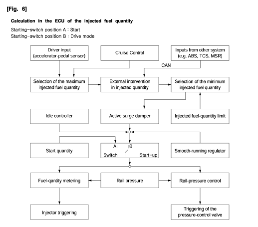
At idle, fuel consumption depends for the most part on engine efficiency and idle speed. Since a considerable portion of a vehicle's fuel consumption in dense traffic conditions is attributable to this operating state, it is obvious that idle speed must be kept to a minimum. The idle speed though, must be set so that no matter what the operating conditions, it does not drop so farunder load that the engine runs roughly or even stops. This applies for instance when the vehicle electrical system is loaded, when the air-conditioner is switched on, when a gear is engaged on an automatic transmission, or when the power steering is in operation. In order to regulate to the desired idle speed, the idle controller varies the injected fuel quantity until the actualengine speed equals the desired idle speed. Here, the desired idle speed and the control characteristic are influenced by the selected gear and by the engine temperature (coolant-temperature sensor). In addition to the external load moments must also be taken into account and compensated for by the idle-speed control. These change minimally but steadily throughout the vehicle's service life, as well as being highly dependent upon temperature.
Due to mechanical tolerance and ageing, there are differences in the torques generated by the engine's individual cylinders. This leads to rough or irregular running, particularly at idle. The smooth-running (cylinder-balancing) control measures the engine-speed changes every time a cylinder has "fired" and compares them with each other. The injected fuel quantity of reach cylinder is then adjusted in accordance with the measured differences in engine speed between the individual cylinders, so that each cylinder makes the same contribution to the torque generated by the engine. The smooth-running control is only operative in the lower engine-speed range.
The vehicle-speed controller (Cruise Control) comes into operation when the vehicle is to be driven at a constant speed. It controls the vehicle speed to that inputted by the driver at the operator unit in the instrument panel. The injected fuel quantity is increased or reduced until the actual speed equals the set speed. While the Cruise Control is in operation, the control process is interrupted if the driver depresses the clutch, or applies the brakes. If the accelerator pedal is pressed, the vehicle can be accelerated beyond the speed which has been set with the Cruise Control. As soon as the accelerator pedal is released, the Cruise Control regulates the speed back down again to the previous set speed. Similarly, if the Cruise Control has been switched off, the driver only needs to press the reactivate key in order to again select the last speed which had been set.
There are a number of reasons why the fuel quantity desired by driver (orthe maximum physically possible quantity) must not be injected.
These include:
Excessive pollutant emissions,
Excessive soot emissions,
Mechanical overloading due to excessive torque or engine speed, or
Thermal overload as a result of excessive coolant, lube-oil, or turbocharger temperature.
The limit for the injected fuel quantity is formed from a number of input variables, for instance intake air mass, engine speed, and coolant temperature.
When the accelerator pedal is abruptly depressed or released, this causes the injected fuel quantity to change rapidly with the result that there is also a rapid change in the torque developed by the engine. These abrupt load changes lead to the resilient engine mountings and the drivertrain generating bucking oscillations which result in fluctuations of engine speed (Fig. 7).
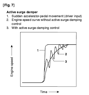
The active surge-damper reduces these periodic speed fluctuations by varying the injected fuel quantity at the same frequency as the periodic speed fluctuations:
Less fuel is injected when the speed increases, and more when it decreases. This effectively damps the surge movements.
The diesel engine operates according to the "auto-ignition" principle. This means that it can only be switched off by interupting its supply of fuel. In the case of the "Electronic Diesel Control (EDC)", the engine is switched off by ECU stipulating "injected fuel quantity zero". The system also features a number of additional (redundant) switch-off paths.
Special injectors with hydraulic servo system and electrical triggering element (solenoid valve) are used with the Common Rail system in order to achieve efficient start of injection and precise injected fuel quantity. At the start of injection, a high pickup current is applied to the injector so that the solenoid valve opens quickly. As soon as the nozzle needle has travelled its complete stroke, and the nozzle has opened completely, the energizing current is reduced to a lower holding value. The injected fuel quantity is now defined by the injector opening time and the rail pressure. Injection is terminated when the solenoid valve is no longer triggered and closes as a result.
For sensor monitoring, the integrated diagnosis facility checks whether they are being supplied with power, and whether their O/P signals are plausible (within the permitted range, e.g. temperature between -40 und 150°C). Where possible, the redundancy principle is applied for important signals. That is, in case of malfunction a switch is made to another similar signal.
In addition to the microcontroller, the ECU also incorporates a monitoring module. The ECU and the monitoring module monitor each other. If a malfunction is detected, either of them can switch off the injection independent of the other.
Malfunction detection is only possible within the monitoring range of a given sensor. A signal path is classified as faulty when an error is present for longer than a predefined period. In such cases, the error is stored in the ECU's error memory together with details of the environmental conditions which prevailed when the error/malfunction occurred (e.g. coolant temperature, enginespeed etc.). For a large number of errors/malfunctions, it is possible for the "OK again" status to be established. Here, the signal path must be identified as intact for a defined period of time.
If a sensor's permitted output-signal range is violated, a switch is made to a substitute value. This procedure is applied for the following input signals:
Battery voltage,
Coolant, air, and lube-oil temperature,
Charge-air pressure,
Atmospheric pressure and intake-air quantity.
In addition, in case of non-plausible signals from the accelerator-pedal sensor and/or the brakes, a substitute accelerator-pedal sensor signal is applied.

The reduction of fuel consumption along with an increase in power output or torque, are the decisive factors behind present-day developments in the diesel fuel-injection field. In the past years this has led to an increase in the use of direct-injection (DI) diesel engines. Compared to prechamber or whirl-chamber engines, the so-called indirect-injection (IDI) engines, the DI engine operates with far higher injection pressures. This leads to improved mixture formation, and fuel combustion is more complete. In the DI engine, the improved mixture formation and the fact that there are no overflow losses between prechamber/whirl chamber and the main combustion chamber results in a fuel-consumption reduction of 10...15% compared to the IDI engine. In addition, modern-day engines are subject to more severe requirements with regard to exhaust-gas and noise emissions.
This has led to higher demands being made on the injection system and its control :
High injection pressures,
Structured rate-of-discharge curve,
Variable start of injection,
Pilot injection,
Adaptation of injected fuel quantity, boost pressure, and injected fuel quantity to the given operating state,
Temperature-dependent start quantity,
Load-independent idle-speed control,
Cruise control,
Closed-loop-controlled exhaust-gas recirculation (EGR), and
Reduced tolerances and higher accuracy throughout the vehicle's useful life.
Conventional mechanical (flyweight) governors use a number of add-on devices to register the various operating conditions, and ensure that mixture formation is of high quality. Such governors, though, are restricted to simple open-loop control operations at the engine, and there are many important actuating variables which they cannot register at all or not quickly enough.
In the past years, the marked increase in the computing power of the micro-controllers available on the market has made it possible for the EDC (Electronic Diesel Control) to comply with the above-named stipulations. In contrast to diesel-enginedvehicles with conventional in-line or distributor injection pumps, the driver of an EDC controlled vehicle has no direct influence, for instance through the accelerator pedal and Bowden cable, upon the injected fuel quantity. On the contrary, the injected fuel quantity is defined by a variety of actuating variables, e.g. operating state driver input, pollutants emission, etc. This of course means that an extensive safety concept must be implemented that detects errors and malfunctions and, depending upon their severity, initiates appropriate countermeasures (e.g. limitation of torque, or emergency (limp-home) running in the idle-speed range) EDC also permits the exchange of data with other electronic systems in the vehicle (e.g. with the traction control system(TCS), and with the electronic transmission-shift control). This means that it can be integrated in the overall vehicle system.
Together with the actuators, the sensors represent the interface between the vehicle and its data-processing unit the ECU.
The signals from the sensors are passed to the ECU (or to several ECU's) via protective circuitry and, where necessary, via signal transducers and amplifiers (Fig. 1) :
Analog input signals (e.g. information from analog sensors on the quantity of air drawn in by the engine, engine and intake-air temperatures, battery voltage, etc.) are converted to digital values by an A/D converter in the ECU microprocessor.
Digital input signals (e.g. On/Off switching signals, or digital sensor signals such as the rotational-speed pulses from a Hall sensor) acan be processed directly by the microprocessor.
In order to suppress interference pulses, the pulse-shaped input signals from inductive sensors which carry information on engine speed and reference mark are conditioned by a special circuit in the ECU and converted to square-wave from.
Depending upon the level of integration, signal conditioning can take place completely or partially in the sensor. The operating conditions encountered at its installation point determine the sensor's loading.
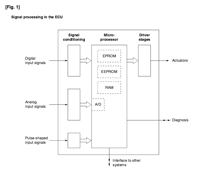
Protective circuitry is used to limit the incoming signals to a maximum voltage level. The effective signal is freed almost completely of superimposed interference signals by means of filtering, and is then amplified to match it to the ECU input voltage.
The ECU microprocessors (Fig. 1) mostly process the input signals digitally, and therefore need a special program. This is stored in a Read Only Memory (ROM or Flash-EPROM).
In addition, engine-specific curves and engine-management maps are stored in a Flash-EPROM. Immobilizer data, calibration and manufacturing data, as well as data on errors/malfunctions which may have occurred during operation are stored in a non-volatile read/write memory (EEPROM).
Due to the large number of engine and equipment variants, the ECU's are provided with a so-called variant code. Using this code, a selection of the maps stored in the Flash-EPROM takes place at the manufacturer or in the workshop, in order to provide the specific functions required for the vehicle variant in question. This selection is also stored in the EEPROM.
Other ECU variants are designed so that complete data sets can be programmed into the Flash-EPROM at the end of vehicle production. This reduces the number of different ECU types required by the vehicle manufacturer.
A volatile random access memory (RAM) is needed to store variable data such as calculations data and signal values. In order to function correctly, the RAM requires a permanent power supply. In other words, it loses its complete data stock when the ECU is switched off via the ignition switch or when the vehicle battery is disconnected. In such cases, the adaptation values (values which have been learnt regarding engine and operating conditions) would have to be re-established when the ECU is switched on again. To prevent this, the adaptation values are stored in an EEPROM and not in a RAM.
With their output signals, the microprocessors trigger output stages which usually are powerful enough for direct connection to the actuators. The triggering of the individual actuators is dealt with in the particular system decription. These output stages are proof against short-circuit to ground or to battery voltage, as well as against destruction due to electrical overload. Such faultsare recognized by the output stages and reported to the microprocessor. This also applies to conductor open-circuits. In addition, a number of the output signals are transmitted through interfaces to other systems in the vehicle.
Sin leakage and heat losses reduce the pressure and the temperature of the A/F mixture at the end of the compression stroke, the diesel engine is more difficult to start and the mixture more difficult to ignite than it is when hot. These facts make it particularly important that start-assist systems are used. The minimum starting temperature depends upon the engine type. Pre-chamber and swirl-chamber engines are equipped with a sheathed-element glow plug in the auxiliary combustion chamber which functions as a "hot spot" On small direct-injection (DI) engines, this "hot spot" is located on the combustion chamber's periphery. Large DI truck engines on the other hand have the alternative of using air preheating in the intake manifold (flame start) or special, easily ignitable fuel (Start Pilot) which is sprayed into the intake air. To day, the start-assist systems use sheathed-element glow plugs practically without exception.
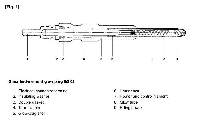
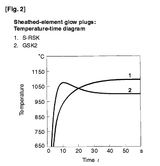
The sheathed-element glow plug's tubular heating element is so firmly pressed into the glow-plug shell that a gas-tight seal is formed. The element is a metal tube which is resistant to both corrosion and hot gases, and which contains a heater (glow) element embedded in magnesium-oxide powder (Fig. 1). This heater element comprises two series-connected resistors: the heater filament in the glow-tube tip, and the control filament. Whereas the heater filament maintains virtually constant electrical resistance regardless of temperature, the control filament is made of material with a positive temperature coefficient (PTC). On newer-generation glow plugs (GSK2), its resistance increases even more rapidly with rising temperature than was the case with the conventional S-RSK glow plug. This means that the newer GSK2 glow plugs are characterized by reaching the temperature needed for ignition far more quickly (850°C in 4s). They also feature a lower steady-state temperature (Fig. 2) which means that the glow plug's temperature is limited to a non-critical level. The result is that the GSK2 glow plug can remain on for up to 3 minutes following engine start. This post-glow feature improves both the warm-up and run-up phases with considerable improvements in noise and exhaust-gas emissions.
The flame glow plug burns fuel to heat the intake air. Normally, the injection system's supply pump delivers fuel to the flame plug through a solenoid valve. The flame plugs's connection fitting is provided with a filter, and a metering device which permits passage of precisely the correct amount of fuel appropriate to the particular engine. This fuel then evaporates in an evaporator tube surrounding the tubular heating element and mixes with the intake air. The resulting mixture ignites on the 1000°C heating element at the flame-plug tip.
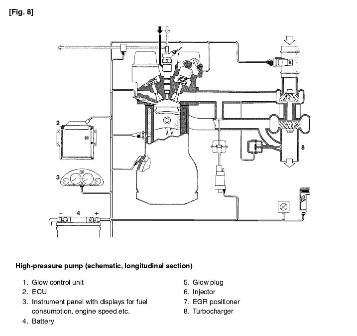
For triggering the glow plugs, glow control unit (GZS) is provided with a power relay and a number of electronic switching blocks. These, for instance, control the glow duration of the glow plugs, or have safety and monitoring functions. Using their diagnosis functions, more sophisticated glow control units are also able to recognise the failure of individual glow plugs andinform the driver accordingly. Multiple plugs are used as the control inputs to the ECU. In order to avoid voltage drops, the power supply to the glow plugs is through suitable threaded pins or plugs.
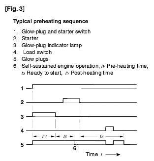
The diesel engine's glow plug and starter switch, which controls the preheat and starting sequence, functions in a similar manner to the ignition and starting switch on the spark-ignition (SI) engine. Switching to the "ignition on" position starts the preheating process and the glow-plug indicator lamp lights up. This extinguishes to indicate that the glow plugs are hot enough for the engine to start, and cranking can begin. In the following starting phase, the droplets of injected fuel ignite in the hot, compressed air. The heat released as a result leads to the initiation of the combustion process (Fig. 3). In the warm-up phase following a successful start, post-heating contributes to faultless engine running (no misfiring) and therefore to practically smokeless engine run-up and idle. At the same time, when the engine is cold, preheating reduces combustion noise. A glow-plug safety switchoff prevents battery discharge in case the engine cannot be started. The glow-control relay can be coupledto the ECU of the Electronic Diesel Control (EDC) so that information available in the EDC control unit can be applied for optimum control of the glow plugs in accordance with the particular operating conditions. This is yet another possibility for reducing the levels of blue smoke and noise.
