
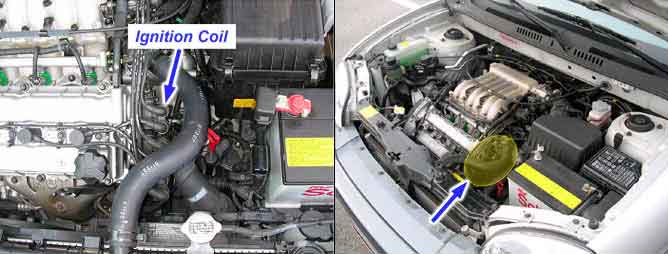
With the ignition switch in the ON or START position, voltage is applied to the ignition coil. Each ignition coil consists of two coils. High tension leads go to each cylinder from the ignition coils. The ignition coils fire two spark plugs on every power stroke (the cylinder under compression and the cylinder on the exhaust stroke). The Engine Control Module (ECM) provides a switching circuit to ground for energizing the primary ignition coils. The ECM uses the crankshaft position sensor and camshaft position sensor signal to time the energizing of the coil. When a primary ignition coil is energized and de-energized, the secondary coil produces a high voltage spike to the attached spark plugs.
The ECM monitors the peak voltage duration of the ignition primary circuit. If abnormal signal is detected on three cylinders or more, the ECM sets DTC P0350
Item | Detecting Condition | Possible Cause |
DTC Strategy | ● Monitoring ignition coil primary voltage | ● Open or short in power supply circuit ● Open or short in control circuit ● Contact resistance in connectors ● Defective ignition coil |
Enable Conditions | ● Coolant temperature >75℃(167℉) | |
Threshold Value | ● Failure on 3 cylinders or more | |
Diagnostic Time | ● 255 revolutions |
Ignition Coil | Normal Parameter at 20℃(68℉) |
Resistance(Primary) | Approx. 0.74 ± 0.07Ω |
Resistance(Secondary) | Approx. 13.3 ± 1.9 (kΩ) |