PRE-WHEEL ALIGNMENT INSPECTION
1.

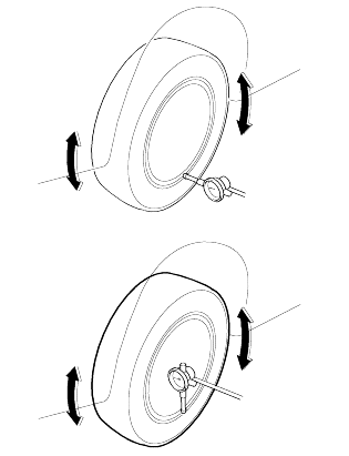
Check and inflate all tires to recommended pressure. See[Cf.]p.SS-28, TIRE INSPECTION. All tires should be the same size and in good condition and have approximately the same wear. Note the type of tread wear which will aidin diagnosing, see [Cf.]p.SS-28, TIRE WEAR.

2.

Check front wheel and tire assembly for radial runout. See[Cf.]p.SS-30, WHEEL RUNOUT.

3.

Inspect lower ball joints and all steering linkage for looseness.

4.

Check for broken or sagged front and rear springs.

5.

Check vehicle ride height to verify it is within specifications.

6.

Alignment MUST only be checked after the vehicle has the following areas inspected and/or adjusted.

FRONT WHEEL ALIGNMENT

Standard value

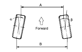
Toe-in (B-A): 0 ± 2 mm (0 ± 0.08 in.)

ADJUSTMENT OF SIDE SLIP AND WHEEL STEERING ANGLE
1.

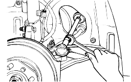
Side slip is adjusted by rotating the tie rod within 0±3mm/m with the vehicle holding one person.

2.

Steering angle is adjusted to the standard value by turning the right and left tie rods in opposite directions for the same amount.

Outer wheel steering angle: 32°73'±2

Inner wheel steering angle (difference between right and left should be within 2°): 37°41'±2°

Inner wheel steering angle variation per tie rod revolution: 0.65°

note

Remove the clip holding the bellows before rotating the tie rod.

Check the bellows for twists after setting the steering angle, then reassemble it.

Tightening torque

Tie rod end lock nut:

50-55 Nm (500-550 kg·cm, 37-41 lb·ft)

Camber: 0°±30'

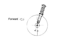
Caster: 2°30'±30'

note
1.

The worn, loose or damaged parts of the front suspension assembly must be replaced before measuring front wheel alignment.

2.

Camber and caster are pre-set at the factory and cannot be adjusted.

3.

If camber and caster are not within specifications, replace bent or damaged parts.

REAR WHEEL ALIGNMENT

TOE-IN

: 0±2 mm (0±0.08 in.)

note
1.

The rear suspension lower arm mounting cam bolt should be turned an equal amount on both sides during adjustment.

Right wheel: Clockwise direction: toe-in

Left wheel: Clockwise direction: ton-out

Maximum difference between LH and RH: 3mm

2.

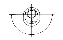
The cam bolt should be adjusted within a 90° range left or right from the center position.

CAMBER

Standard value: 0°±30'

Maximum difference between LH and RH: 3mm

note
1.

The rear suspension upper arm mounting cam bolt should be turned an equal amount on both sides during adjustment.

2.

Install the left and right springs which have the same identification color.

3.

The cam bolt should be adjusted within a 90° range left and right from the center position.
WHEEL RUNOUT
1.

Lift the vehicle up and support it with jack stands.

2.

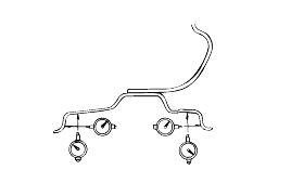
Measure wheel runout with a dial indicator as illustrated.

3.

Replace the wheel if wheel runout exceeds the limit.

Wheel runout [Limit]

Aluminum wheel:

Radial - 0.3mm (0.012 in)

Axial - 0.3mm (0.012 in)

TIGHTENING WHEEL NUT
1.

Tightening torque

90-110 Nm (900-1100kg·cm, 66-81 lb·ft)

note

When using an impact gun, keep strictly the correct tightening torque.

2.

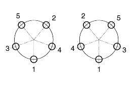
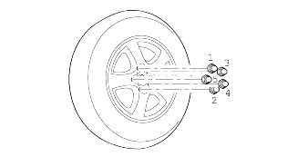
Tighten all wheel nuts completely in the order illustrated.

Яндекс.Метрика