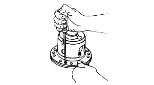
Using the torx screw driver #T27, remove the 4 torx screws on the flange.
Before removal, make matchmarks.
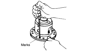
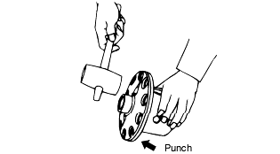
If the case halves are not separated, tap the heads of the screws lightly with a punch and a hammer as shown in illustration.
Using the torx screw driver #T27, remove the 4 torx screws on the flange.
Before removal, make matchmarks.

If the case halves are not separated, tap the heads of the screws lightly with a punch and a hammer as shown in illustration.

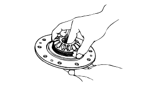
Remove the screws, L.H. case, L.H. shim, L.H. gear sub-assembly (side gear, disc pack, and ear guides), preload plate and two preload springs fromthe R.H. case assembly.
Keep these parts separate so that they can be reassembled in the same location as they were originally.
Drive out the cross shaft lock pin using a 4 mm diameter rod and a hammer.
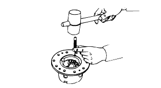
Remove the cross shaft from the side gear.
The cross shaft must be driven toward the side where the lock pin hole is located as shown in the illustration.
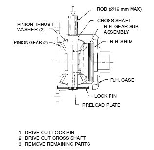
Follow the same procedure for the opposite side case.
Do not mix R.H. and L.H. parts.
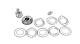
Check the side gears, pinions, pinion thrust washers, and cross shaft for wear or damage. If there is excessive wear, cracks, nicks, groovesor galling, replace the parts.
Inspect the carbon surfaces. After cleaning with a solvent, the carbon surface should appear a course weave fabric with flat spots on thepeaks of the weave.
If the surface is smooth, either from wear or from the weave filled with debris, replace the entire disc pack.
Measure the thickness of the carbon friction discs.
If the measurements is below the limit value, replace the disc.
Clutch discs | Limit value |
Double sided discs | 2.06 mm (0.081 in.) |
Single sided disc | 1.65 mm (0.065 in.) |
Inspect the splined friction discs. If they have grooves or are polished, replace the entire disc pack. Small scratches on them are O.K.
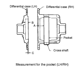
Measurement for R.H. pocket
Measure the R.H. pocket with the pinion shaft installed as shown in illustration.
Measurement for L.H. pocket
Measure the L.H. pocket with the pinion shaft installed according to the following formula as shown in illustration.
L.H. POCKET = A + B - C
Measurement for the side gear sub height.
As shown in illustration, install the clutch disc, side gear, preload spring and spring plate, and then adjust the clearance of the preload spring by applying the pressure at both sides till it is 32mm as shown in illustration. At this time, measure the height of side gear sub at RH, LH sides by measuringthe length of "D"
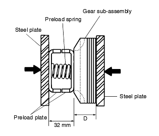
Seclecting shims by the side gear sub height
Used disc
Shim thickness = RH(LH) pocket - RH(LH) side gear sub height - 6.45
New disc
Shim thickness = RH(LH) pocket - RH(LH) side gear sub height - 6.20
Adjust the shim thickness within 0.08mm.
When replacing one disc, replace all of the discs.
The specifications of the clutch disc shim
Part No. (EATON No.) | Shim thickness |
EDS98754 - 10 | 0.010' |
EDS98754 - 15 | 0.015' |
EDS98754 - 20 | 0.020' |
EDS98754 - 30 | 0.025' |
EDS98754 - 35 | 0.030' |
EDS98754 - 40 | 0.035' |
EDS98754 - 45 | 0.040' |
Install the clutch disc guide and clutch disc in order.
Apply grease to the clutch disc guide and clutch disc before reassembly.
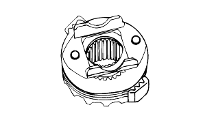
Install the clutch preload plate and side gear.
After assembling the pinion shaft, pinion gear and washer, fix the pinion shaft lock pin with a hammer.
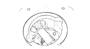
Install the preload spring and spring plate in the opposite side .
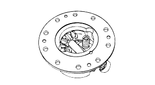
After assembling the clutch disc and side gear in the opposite case, assemble the two cases.
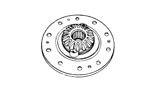
Assemble the case by tightening the torx screws.
