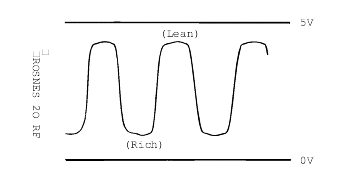
While repeatedly racing the engine, measure the oxygen sensor output voltage.
Engine | Oxygen sensor output voltage | Remarks |
Race | 4000~4500mV | Makes the air/fuel mixture rich by increasing engine speed |


If the HO2S is defective, abnormally high emissions may occur.
If the HO2S check results were normal, but the sensor output voltage is out of specification, check for the following items (related to air fuelratio control system):
● Defective injector ● Air leaks in the intake manifold. ● Defective air flow sensor, intake air temperature sensor, and engine coolant temperature sensor. |
Check Item | Check conditions | Engine state | Test specification |
Oxygen sensor | Engine: Warm-up (make the mixture lean by engine speed reduction, and rich by racing) | When sudden deceleration from 4,000 rpm | 4000~4500 mV |
When engine is suddenly raced | 500~1000 mV | ||
Engine: Warm-up (using the heated oxygen sensor signal, check the air/fuel mixture ratio, and alsocheck the condition of control by the PCM) | At Idle rpm | 500~4500 mV | |
2,000 rpm | 500~4500 mV |
Disconnect the oxygen sensor connector, and measure the resistance between terminal 3 and terminal 4.
Temperature °C (°F) | Resistance (Ω) |
23 | 4.0 ~ 5.2 |
400 (752) | 8.2 ~ 11.1 |
Before checking, warm up the engine until the engine coolant temperature reaches 80 to 95°C (176 to 205°F).
Apply battery voltage directly between terminal 3 and terminal 4.
Be careful when applying the voltage. Damage will result if the terminals are incorrect or are short circuited.
Connect a digital-type voltmeter between terminal 1 and terminal 2.
While repeatedly racing the engine, measure the oxygen sensor output voltage.
Engine | Oxygen sensor output voltage | Remarks |
Race | 4000~4500mV | Makes the air/fuel mixture rich by increasing engine speed |

If there is a problem, there may be an oxygen sensor malfunction.
Tightening torque Heated oxygen sensor : |
40~50 Nm (400~500 kg·cm, 29~36 lb·ft) |


