Rmove the cylinder head bolts in the order shown in the illustration.
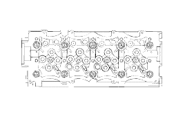
Rmove the cylinder head bolts in the order shown in the illustration.

Using the special tool (09222 - 27300) remove the valve spring retainer lock. Then remove the spring retainer, valve spring, spring seat and valve.
Arrange these parts so that they can be reinstalled in their original positions.
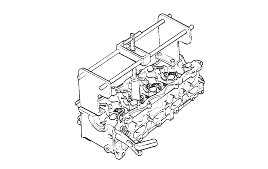
Remove the valve stem seals with pliers.
Do not reuse the valve stem seals.

Check the cylinder head for cracks, damage and coolant leakage. If cracked, replace the cylinder head.
Remove scale, sealing compound and carbon deposits completely. After cleaning the oil passages, apply compressed air to verify that the passagesare not clogged.

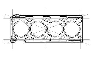
Check the cylinder head surface for flatness in the direction as shown in the illustration. If flatness exceeds service limit in any direction, either replace the cylinder head or machine the cylinder head matching surfacelightly.
Flatness of cylinder head gasket surface |
Standard : 0.03 mm (0.0012 in.) |
for width 0.09 mm (0.0035 in.) for length) |
0.012 mm (0.00047 in.) / 51 x 51 |
Using a wire brush, clean the valve thoroughly.

Check each valve for wear, damage and distortion of the head and the stem at B Position. Replace, if necessary. If stem end, A, is hollowed out or worn, resurface as necessary. This correction must be limited to aminimum. Also resurface the valve face.
Replace the valve if the margin has decreased to less than the service limit.
Margin |
[Standard] |
Intake : 1.6 mm (0.063 in.) |
Exhaust : 1.3 mm (0.0512 in.) |

Check the free height of each valve spring. If they exceed the service limit, replace the springs.
Using a square, test the squareness of each spring. If a spring is excessively out- of-square, replace it.
Valve spring |
[Standard] |
Free height : 39.14 mm(1.54 in.) |
Load : 21.4 kg / 32 mm (47.2 lb / 1.26 in.) |
Out of square : 1.5° or less |
[Limit] |
Free height : 38.14 mm (1.50 in.) |
Out of square : 4° |

Valve stem - to - guide clearance |
[Standard] |
Intake : 0.022 - 0.067 mm (0.00086 - 0.0026 in.) |
Exhaust : 0.05 - 0.095 mm (0.0020 - 0.0037 in.) |
[Limit] |
Intake : 0.1 mm (0.0040 in) |
Exhaust : 0.15 mm (0.0059 in.) |

Clean each part before assembly.
Apply engine oil to the sliding and rotating parts.
Install the spring seats.
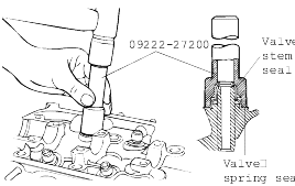
Using a special tool (09222 - 27200), tap the seal in position lightly.
Do not reuse old valve stem seals.
Incorrect installation of the seal could result in oil leakage past the valve guides.
Apply engine oil to each valve. Insert the valve into the valve guide. Avoid pushing the valve into the seal by force. After inserting thevalve, check that it moves smoothly.
Place valve springs so that the side coated with enamel faces the valve spring retainer and then install the retainer.

Using the special tool (09222 - 27300), compress the spring and install the retainer locks. After installing the valves, ensure that the retainer locks are correctly in place before releasing the valve spring compressor.

When the spring is compressed, Check that the valve stem seal is not pressed against the bottom of the retainer.
Clean both gasket surfaces of the cylinder block and cylinder head.
Select the cylinder head gasket.
Measure the piston protrusion from the upper cylinder block face on 8 places at T.D.C. Measure on the crankshaft center line considering thepiston migration.
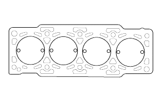
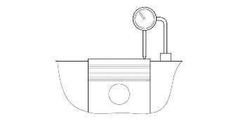
Select the gasket in the table below using the average value of 8 piston protrusions.
Even if only 1 point is over than the limit of piston protrusion at each grade, 1 grade upper gasket than specified below.
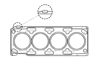
Displacement | 2.0 L | ||
Average of pisston protrusion | 0.194 - 0.337 mm (0.0076 - 0.013 in.) | 0.337 - 0.440 mm (0.013 - 0.017 in.) | 0.440 - 0.542 mm (0.017 - 0.021 in.) |
Gasket thickness | 1.13 ± 0.05 mm (0.0445 ± 0.0019 in.) | 1.23 ± 0.05 mm (0.0484 ± 0.0019 in.) | 1.33 ± 0.05 mm (0.0523 ± 0.0019 in.) |
Limit of each rank extant | 0.43 mm (0.0169 in.) | 0.53 mm (0.0208 in.) | - |
Identification code |  |  |  |
Install the gasket so that the surface with the identification mark faces toward the cylinder head.
Tighten the bolts to the specified torque.
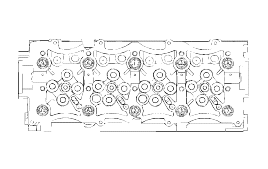
Tightening torque : |
50 Nm (500 kg.cm, 36.9 lb.ft) + 120° + +90° |