Line up the front marks and insert the piston pin. The piston pin must be smoothly pressed by hand into position. Replace the piston pin ifthere is excessive play.
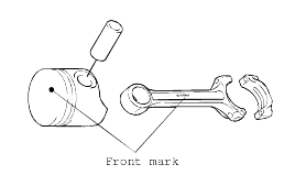
Match the piston with the connecting rod.
Line up the front marks and insert the piston pin. The piston pin must be smoothly pressed by hand into position. Replace the piston pin ifthere is excessive play.

Install the oil ring expander and oil ring to the piston. Then, install No.2 piston ring and No.1 piston ring, in that order. Make sure that the ring side, on which manufacturer and size marks are stamped, faces tothe piston crown.
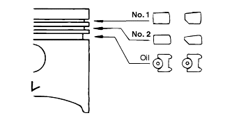
Position ends of piston and oil (side rail, spacer) rings as illustrated.
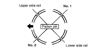
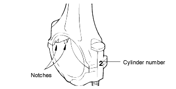
Insert the piston and connecting rod assembly from above the top of cylinder. Ensure that the front mark on piston crown and that (ID mark) on the connecting rod face toward the front of engine (to the crank pulleyside).
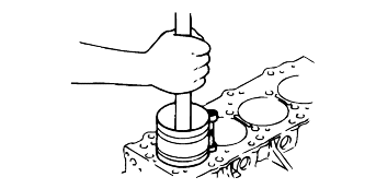
Clamp firm the piston rings with the ring band and install the piston assembly into cylinder. Do not strike it hard into the piston, as broken pistonring or damaged crank pin could result.
Tighten the connecting rod cap bolts.
Tightening torque |
Connecting rod cap bolts : |
25 Nm (250 kg·cm, 18·4 lb·ft) + 90° |
Re-use of the bolt must be limited to 3 times.
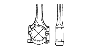
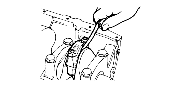
Make sure the clearance of connecting rod big end side.
Check each piston for scuffing, scoring, wear and other defects. Replace any piston that is defective.
Check that the piston pin fits in the piston pin hole.
Replace any piston and pin assembly that is defective.
The piston pin must be smoothly pressed by hand into the pin hole (at room temperature)
Check each piston ring for breakage, damage and abnormal wear.
Replace the defective rings.
When the piston requires replacement, its ring should also be replaced.
Measure the clearance between piston ring and ring groove.
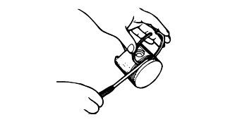
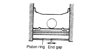
Place a piston ring in the cylinder bore and set it square by pushing it down with piston.
Measure the end clearance using a thickness gauge.
Check the bearing surfaces for uneven contact pattern, streaks, scratches, and seizure. If defects are evident, replace. If the surfaces are seriously nicked and seized, check also the crankshaft. If the crankshaft is also damaged,replace the crankshaft or grind to undersize for reuse.
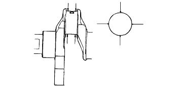
Measure the connecting rod bearing I.D. and crankshaft pin O.D. If the clearance (oil clearance) exceeds the limit, replace the bearing and, if necessary, the crankshaft. Or, grind the crankshaft to an undersize and, at the sametime, replace the bearing with an undersize.
Check the bearing surfaces for uneven contact pattern, streaks, scratches, and seizure. If defects are evident, replace. If the surfaces are seriously nicked and seized, check also the crankshaft. If the crankshaft is also damaged,replace the crankshaft or grind to undersize for reuse.
