Terminal and Connector Inspection
1.

Many malfunctions in the electrical system are caused by poor harness(s) and terminals. Faults can also be caused by interference from other electrical systems, and mechanical or chemical damage.

2.

Check the following conditions:

(1)

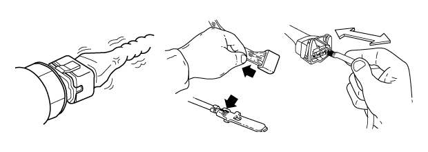
Check for damaged harness and terminals: contact resistance, oxidation, bent or broken terminals.

(2)

Check for poor connection between ECM and component: backed out terminal, improper mating, broken locks or poor terminal to wire connection

note

Use a suitable male pin to ensure that contact in sockets is good. The pin should remain in position when pulled gently.
3.

Has a problem been found?

YES

a.

Repair as necessary and go to “Verification of Vehicle Repair” procedure

NO

a.

Fault is intermittent caused by poor contact in the sensor's and/or PCM's connector or was repaired and PCM memory was not cleared.

b.

System OK

Power Supply Circuit Inspection
1.

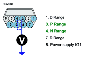
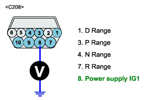
CHECK POWER TO RANGE SWITCH ,

(1)

Turn ignition switch to ON position and disconnect RAGE SWITCH connector

(2)

Measure voltage between terminal 8 of the RANGE SWITCH harness connector and chassis ground.

1)

Specification : Approximately B+

2.

CHECK REFERENACE VOLTAGE TO RANGE SWITCH

(1)

Turn ignition switch to ON position and disconnect RANGE SWITCH connector

(2)

Measure voltage between terminal 3,4 of the RANGE SWITCH harness connector and chassis ground.

1)

Specification : Approximately B+

3.

Is votage within specification ?

YES

a.

Go to "CHECK TCM " of the "Component Inspection" procedure.

NO

a.

Repair open in harness and go to “Verification of Vehicle Repair” procedure.

b.

If harness is OK, Go to "CHECK RANGE SWITCH" Component Inspection" procedure

Signal Circuit Inspection
1.

CHECK POWER TO PCM

(1)

Turn ignition switch to ON position and disconnect PCM connector

(2)

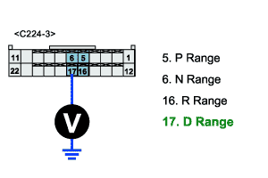
Measure voltage between terminal 2 of the PCM harness connector and chassis ground.

1)

Specification : Approximately B+

2.

Is voltage within specification?

YES

a.

Go to “PCM inspection ”of the “Component Inspection” procedure.

NO

a.

Repair open in harness between Inhibitor SW 1/ C09 Terminal and PCM 2/ C44-4 Terminal and Go to "Verification of Vehicle Repair" procedure.

b.

If harness is OK, Go to “Component Inspection” procedure

caution

Above is an example which input signal of D-range is not produced. In similar case follow same way

Яндекс.Метрика