Using the special tool (09545-3A000, 09216-21100), remove the lower arm (G) bushing.
Remove the wheel.
Loosen the bolt mounting the knuckle and the lower arm ball joint.
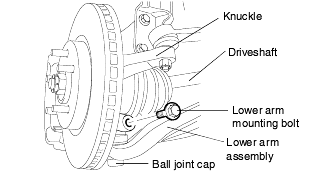
Remove the (A) and the (G) bushing mounting bolts from the sub frame.
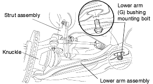
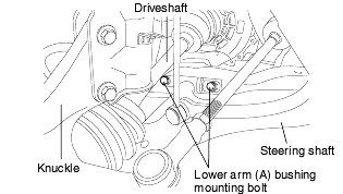
Using the special tool (09545-3A000, 09216-21100), remove the lower arm (G) bushing.

Using a screwdriver, remove the dust cover from the lower arm ball joint.
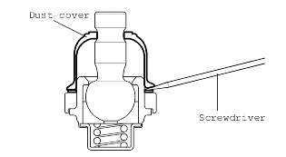
Remove the snap ring.
Using a plastic hammer, remove the ball joint from the lower arm assembly.
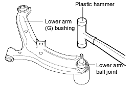
Check the bushing for wear and deterioration.
Check the lower arm for bends and other damage.
Check the ball joint dust cover for cracks. If there is a crack on the dust cover, replace the ball joint assembly.
Check the lower arm connecting bolt.
Shake the ball joint stud several times to test for looseness.
Check the lower arm ball joint rotating torque.
Standard value 1.0-3.5 Nm (10-35 kgf·cm, 0.7-2.6 lb·ft) MAX. |
Measure the lower arm ball joint rotating torque at the 0.5-2 rpm angular speed oscillating 3° at room temperature after 24 hours from completionassembly.
When the rotating torque is above the maximum standard value, replace the ball joint assembly.
When the rotating torque is less than the minimum standard value, the ball joint may be used again if there is no wear in the ball joint.
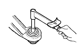
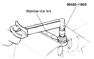
Check the stabilizer bar link ball joint for rotating starting torque.
If there is a crack on the dust cover, replace the ball joint dust cover and apply grease.
Shake the stabilizer link ball joint several times to test for looseness.
Install the self locking nut on the ball joint and measure the ball joint rotating starting torque.
Standard value 0.7-2 Nm (7-20 kg·cm, 0.52-1.5 lb·ft) |
After 24 hours from completion assembly, rotate the ball joint stud to the left and right five times.
Afterwards, measure the rotating starting torque around the range of 2 rpm at room temperature.
If the rotating starting torque is above the maximum standard value, replace the stabilizer link.
If the rotating starting torque is less than the minimum standard value and there is no ball joint abnormal wear or excessive gap, the ball jointmay be used again.
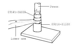
Using the special tool (09545-3A000, 09216-21100), press-fit the lower arm (G) bushing.
The standard pull-out force for the bushing: more than 50 N [500 kg(f), 1103 lb(f)].

Supporting the ball joint flange, press down the lower arm bushing until the flange touches the lower arm surface.
Do not press the ball joint cap.
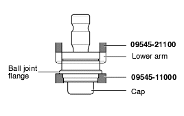
Using a snap ring plier, install the snap ring. Keep the amount of the snap ring expansion as small as possible.
Apply multi-purpose grease to the dust cover lip and inside the cover.
Grease: Sunlight MB-2 or LUBCHEM SB 6042M |
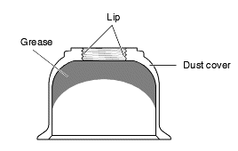
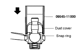
Using the special tool (09545-11000), install the dust cover until it is completely seated on the snap ring.
